
I decided to play with a familiar watch crystal – a 32.768 kHz tuning-fork quartz – but without using a convenient microcontroller or crystal oscillator IC. The goal was purely educational: to learn how crystal oscillators really work (phase shift, loading, gain, etc.) by building one from scratch with transistors. I wanted to see if I could reproduce a simple Pierce oscillator behavior (normally done with a single CMOS inverter) using discrete BJT amplifiers. What follows is the full story – the theory, the measurements, the failures, and the fixes – in hopes that others might find it interesting.
How a Quartz Crystal Resonator Works
A quartz crystal is an electromechanical resonator that’s modeled as a small series R–L–C motional branch (Ls, Cs, Rs) in parallel with a static capacitance C0 (the electrodes/holder).
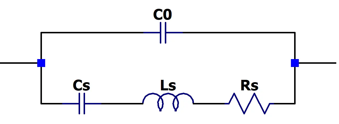
This topology produces two closely spaced resonant frequencies: the series resonance fs (where Ls and Cs‘s impedances cancel and the crystal’s impedance falls to Rs) and the parallel resonance fp (slightly above fs, where the motional branch resonates with C0 and the impedance is high). Immediately above fs the motional branch appears inductive until it reaches fp, and outside the band (below fs or above fp) the crystal looks capacitive. In practical oscillator circuits (especially the common Pierce topology) the crystal does not run exactly at the pure series or pure parallel resonant frequency but between fs and fp — typically closer to fs — which allows the designer to use fine adjustments to load capacitors which calibrates the operating frequency to the final specified value.
If you want a deeper dive into how a crystal resonator works. I recommend you check out this excellent post over at Altium: https://resources.altium.com/p/making-most-your-crystal-oscillator
Goals for the build
- Oscillation frequency matches the datasheet.
- Keep crystal drive within 1μW (Above this damages the crystal)
- Operate from a 5V logic rail (3.3 V desirable).
- Current draw as low as possible
Crystal Measurements
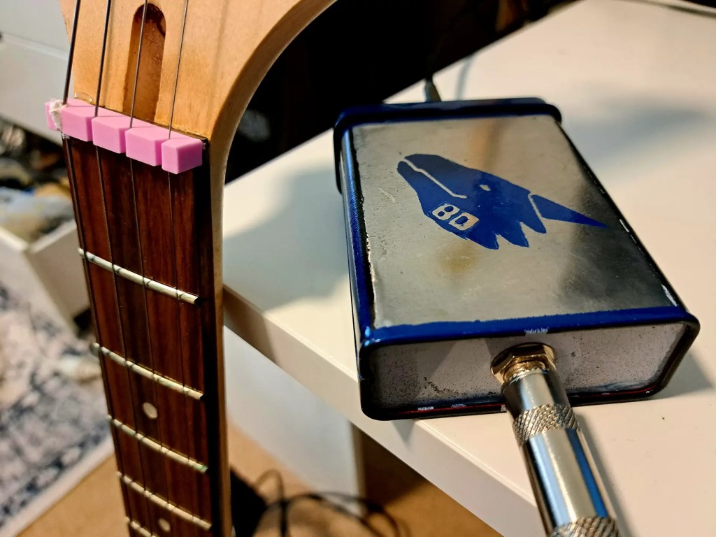
I bought the following crystals from AliExpress https://s.click.aliexpress.com/e/_c3YyCnl7 and when they arrived. I first set about measuring them with the following circuit.
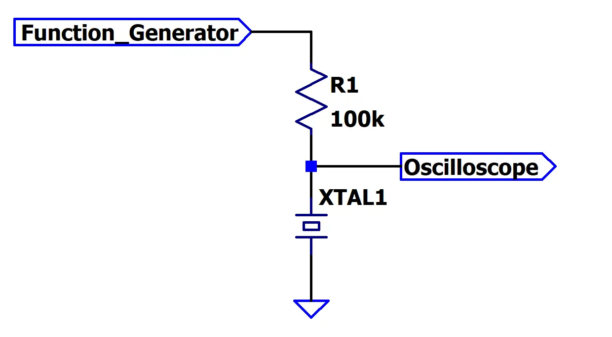
Sweeping my function generator slowly from 30kHz upward. I took note of the frequencies that produced the maximum voltage. As expected from our thory, there are is a minima and a maxima very close together in frequency. I measured these to be.
Fs Series resonance, the minima: 32.764 kHz
Fp Parallel resonance, the maxima: 32.770 kHz
A datasheet for the crystal gives the following additional parameters:
- Cs: 1.2fF (femto farads)
- Rs: 30kΩ
- C0: 1.2pF
- Expected load capacitance: 12.5pF
Using the series value together with the resonance frequencies, I can solve for the remaining unknown parameter required to complete the small-signal model:
- Ls: 19658.897H
It’s immediately obvious that the motional capacitance is extraordinarily small and the motional inductance is correspondingly huge. That’s normal: these parameters are a model of the crystal’s mechanical motion rather than its intrinsic electrical properties. The tiny value of Cs reflects the fact that only a very small amount of electrical energy transfers into (Or out of) the crystal’s mechanical vibration per cycle.
With these values in-hand, It’s possible to create a SPICE model of the crystal. I’m including it here in case anyone finds it useful.
* 32768 Hz crystal model - motional branch + shunt C0
* Nodes: 1 = crystal terminal A, 2 = crystal terminal B
    LS   1  3  1.9658897e4
    CS   3  4  1.2e-15
    RS   4  2  3.0e4
    CO   1  2  1.2e-12
Pierce Oscillator
The circuits I am going to try are all variations of a Pierce oscillator. A Pierce oscillator starts from a simple premise: you have an inverting amplifier (U1) that inherently contributes 180° of phase shift, and you need another 180° provided by the feedback network to meet the 360° oscillation condition. The crystal, together with its two load capacitors (C1, C2), supplies that additional phase shift near its operating point.
The amplifier must also supply enough loop gain to overcome the crystal’s motional resistance, so the overall gain at the operating frequency can exceed unity. Once both conditions are met—360° total phase shift and loop gain > 1—the circuit naturally starts oscillating and settles at the crystal’s frequency fine-tuned by the load capacitance.

Sources (like the datasheet) will assume the crystal is paired with CMOS logic IC (typically a CMOS inverter, U1 above), which operates an order of magnitude faster, and has lower parasitic capacitance than a discrete transistor stage. As our single BJT is no where near as ideal an amplifier as a CMOS IC, we can expect some (Or even a lot of) trouble. If our discrete amplifier adds too much lag, we’re pushed toward using larger load capacitors to recover the required phase shift, and that pulls the oscillator toward an incorrect operating frequency.
Attempt 1
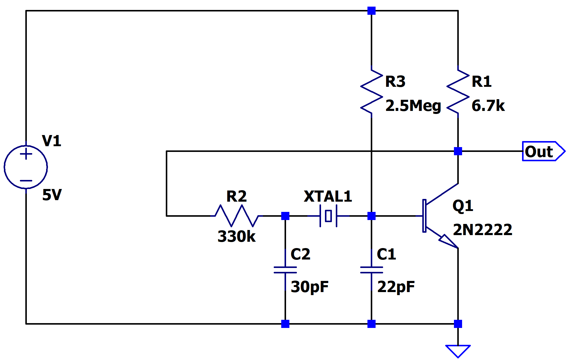
To make the frequency tunable, I used a 30 pF varicap as the load capacitor C2. R2 is in series with the crystal to limit power and keep it under 1 µW, protecting it from damage. The 2.5 MΩ bias resistor was a potentiometer, adjusted to set the output node to about half the rail voltage.
Ideally, the collector resistor R1 could be larger, but 6.7 kΩ was the highest I could go while still keeping bias currents reasonable. At very low currents, the gain drops below what’s needed for oscillation. With the values I used, the DC gain comes out roughly to:
(2.5/6.7kΩ)/(4.3/2.5MΩ)≈192
With this configuration, the oscillator runs at a frequency of about 37.764 kHz — far off the 32.768 kHz target. That’s a 122 parts-per-million error; if I used this for a clock, it would lose about 10 seconds per day. But the datasheet specifies an absolute accuracy of 20ppm. Essentially, it’s resonating almost exactly at the series resonant frequency measured earlier rather than between the series and parallel resonant frequencies as intended.
So what went wrong? Is the problem too little or too much load capacitance? Looking at the relationship between series frequency Fs and load capacitance:
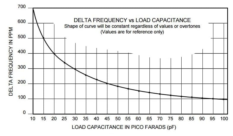
I see that increasing the load capacitance lowers the frequency toward the series resonance. Since my frequency is already too low, that means I actually have too much load capacitance. But even at the lowest varicap setting that still allows oscillation to start, the frequency is still too low.
Attempt #1 is a bust — I can’t hit the target frequency with this topology.
I believe the main culprit is the Miller effect. On paper, the 2N2222’s input and output capacitances should be small enough, but with my loop gain of 192, the effective output capacitance seen by the crystal becomes ~192 pF (1 pF × 192), far exceeding the intended load capacitance of ~12.5 pF. That’s way too high, and it destroys the phase margin I need for oscillation.
It’s worth noting that even with in optimal conditions, this circuit is barely functional. We’ve configured this circuit for maximum gain, and minimum phase lag, but it still barely oscillates. On top of that, this circuit is highly sensitive to choice of transistor, temperature, and power supply voltage. It absolutely can not be recommended for any practical use aside from education. Expect a lot of trouble getting it to oscillate if you try to replicate this circuit.
To give you an idea of how marginal the conditions are, the startup of this oscillator is painfully slow — it takes tens of seconds in real time to build up to a stable amplitude. More than once I had everything wired correctly and still thought the circuit wasn’t working, simply because I didn’t wait long enough for the oscillations to develop. Frustrating!
So, finally, a summary of what was achieved with this circuit:
| Oscillates at 5V | Yes |
| Oscillates at 3.3V | Yes |
| Current draw at 5V | 793μA |
| Current Draw at 3.3V | 290μA |
| Startup time | 18 seconds |
| Frequency Accurate? | No (120ppm error, can’t be calibrated) |
In the next post, I’ll try another circuit that tackles some of these issues by using a more complex transistor topology to reduce the input and output capacitances and increase the overall loop gain.

Leave a comment