
Both the RTL-SDR Blog V3 and V4 are low-cost software-defined radios capable of receiving a wide range of frequencies, including the AM broadcast band. However, neither includes an antenna suitable for AM reception out of the box. The most common advice online is to use a long-wire antenna, but this isn’t always practical, especially if space is limited.
Traditional AM radios often work just fine using a simple ferrite loop-stick antenna. Why not the RTL-SDR? Instead of stringing up a long wire, I decided to experiment with using an AM loop-stick antenna with my RTL-SDR Blog V3 to see how well it performs.
Parts you’ll need
- SMA Male to BNC Female (AliExpress | Amazon)
- RG58 BNC Male to Male cable (AliExpress | Amazon)
- BNC Female Panel Mount Connector (AliExpress | Amazon)
- 0.30mm Enamel/Magnet Wire (AliExpress | Amazon)
- An RTL-SDR Blog V4 (Amazon)
You’ll also need one of the following ferrite rods:
- Manganese Zinc Ferrite Rod (AliExpress | Amazon) for frequencies only below 2MHz
- Nickel Zinc Ferrite Rod (AliExpress | Amazon) for frequencies 500kHz to 10MHz
Notes on Ferrite Rod Selection
Rod length matters
Longer ferrite rods generally provide higher sensitivity, but they are also more directional. Maximum signal is received when the long axis of the rod is perpendicular to the direction of the transmitting station. A 100 to 200mm rod will work.
Manganese-Zinc (MnZn) ferrite
This is the standard material used in AM broadcast receivers. It offers excellent sensitivity in the medium-wave band (approximately 530–1700 kHz), but performance drops off rapidly above about 2 MHz.
Physically, MnZn ferrite often appears slightly sparkly when rotated under bright light and typically has a coarse, sandpaper-like surface texture.
Nickel-Zinc (NiZn) ferrite
NiZn rods work over a much wider frequency range, making them useful for experimentation into the HF bands. However, they are typically less sensitive than MnZn rods in the AM broadcast band.
NiZn ferrite has a smooth, matte finish, often resembling graphite pencil lead. Unlike MnZn ferrite, it does not sparkle under bright light.
Assembly Instructions
The instructions for this one are pretty straight forward:
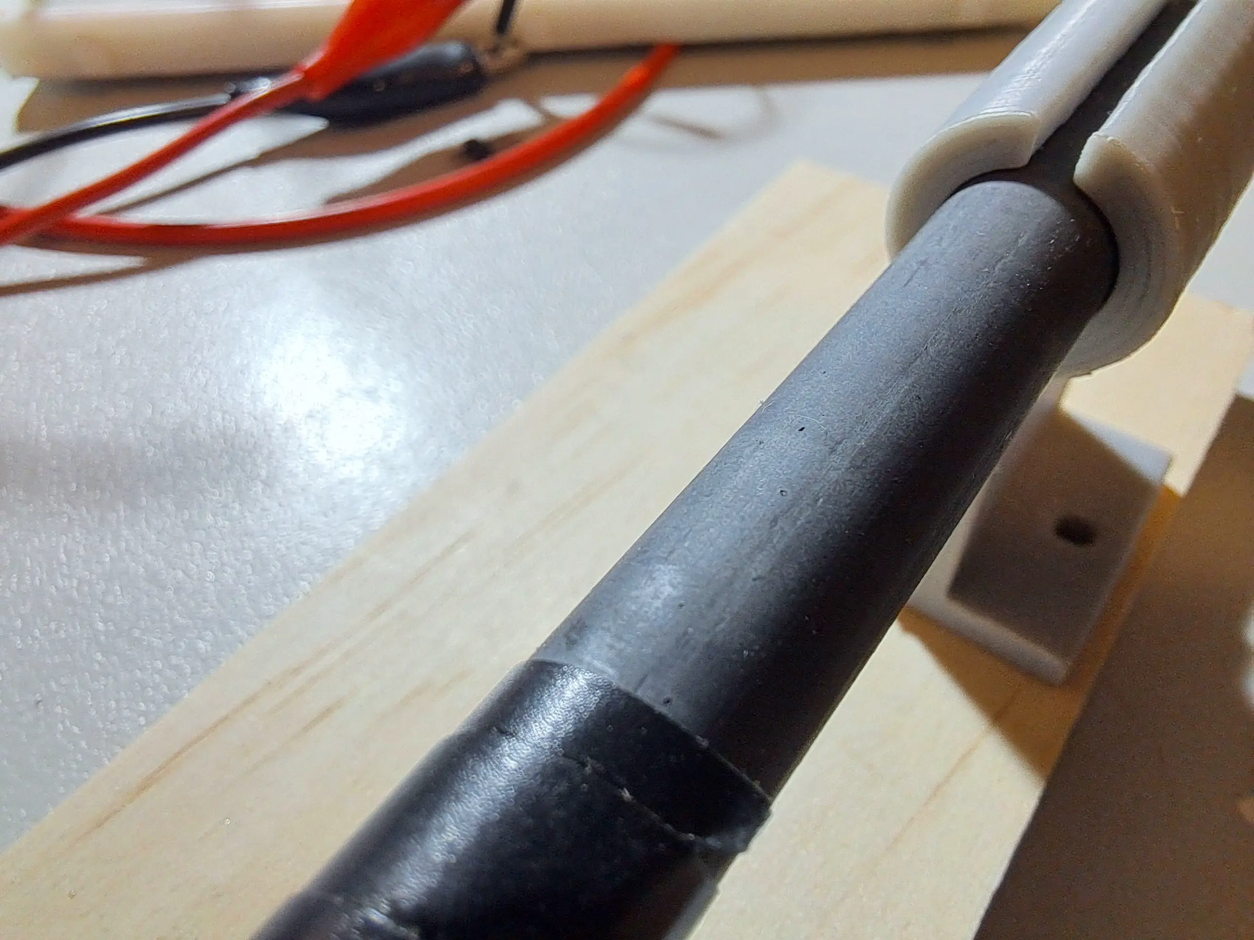
- Wrap some tape around the middle of the ferrite rod to protect the wire from abrasion.
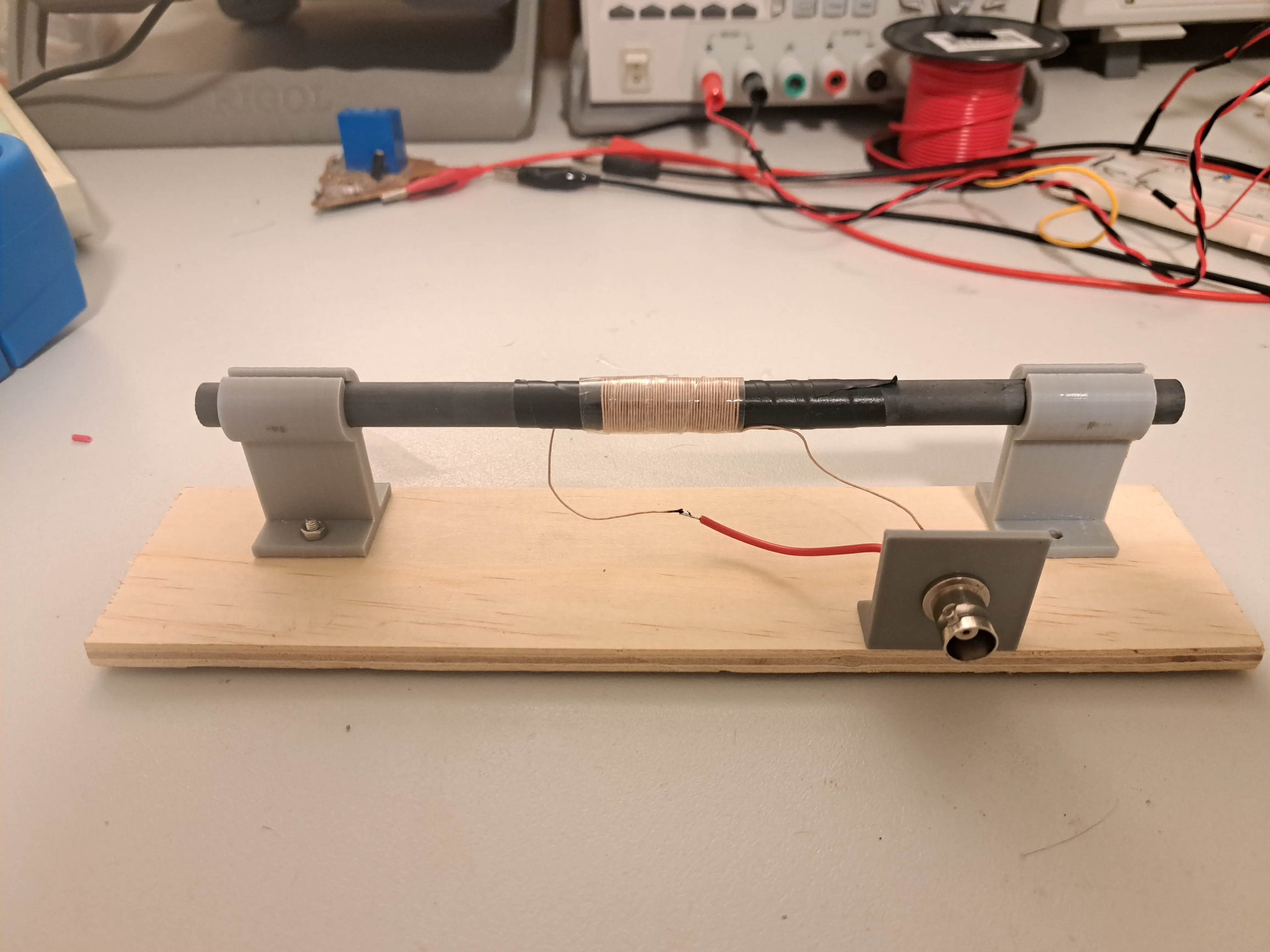
- Wind approximately 40 turns of enamel wire around the center of the ferrite rod.
- Mount the rod so it is supported at both ends and kept away from nearby metal objects.
- Ferrite rods are ceramic and fragile—handle them carefully, as they can crack easily.
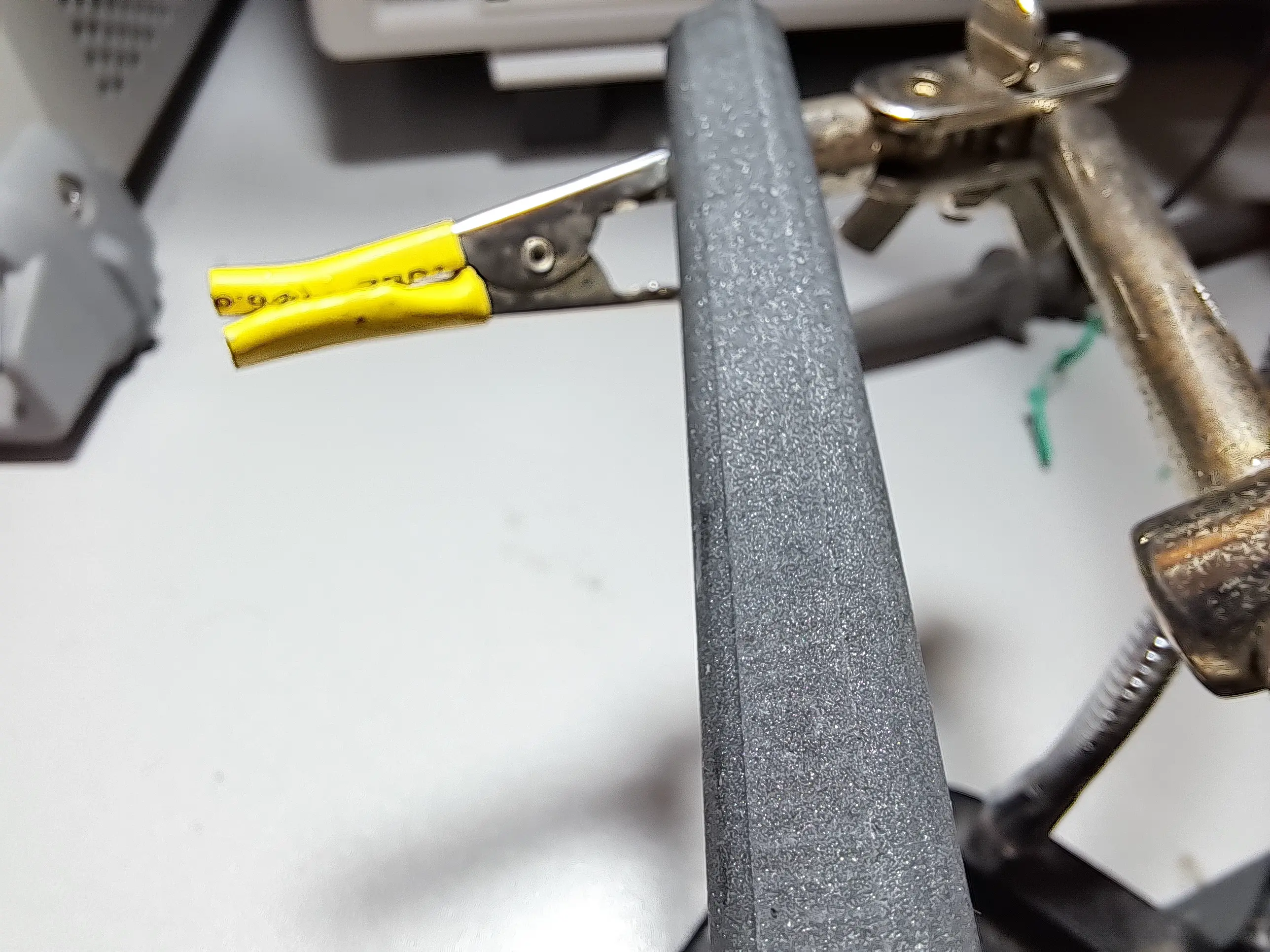
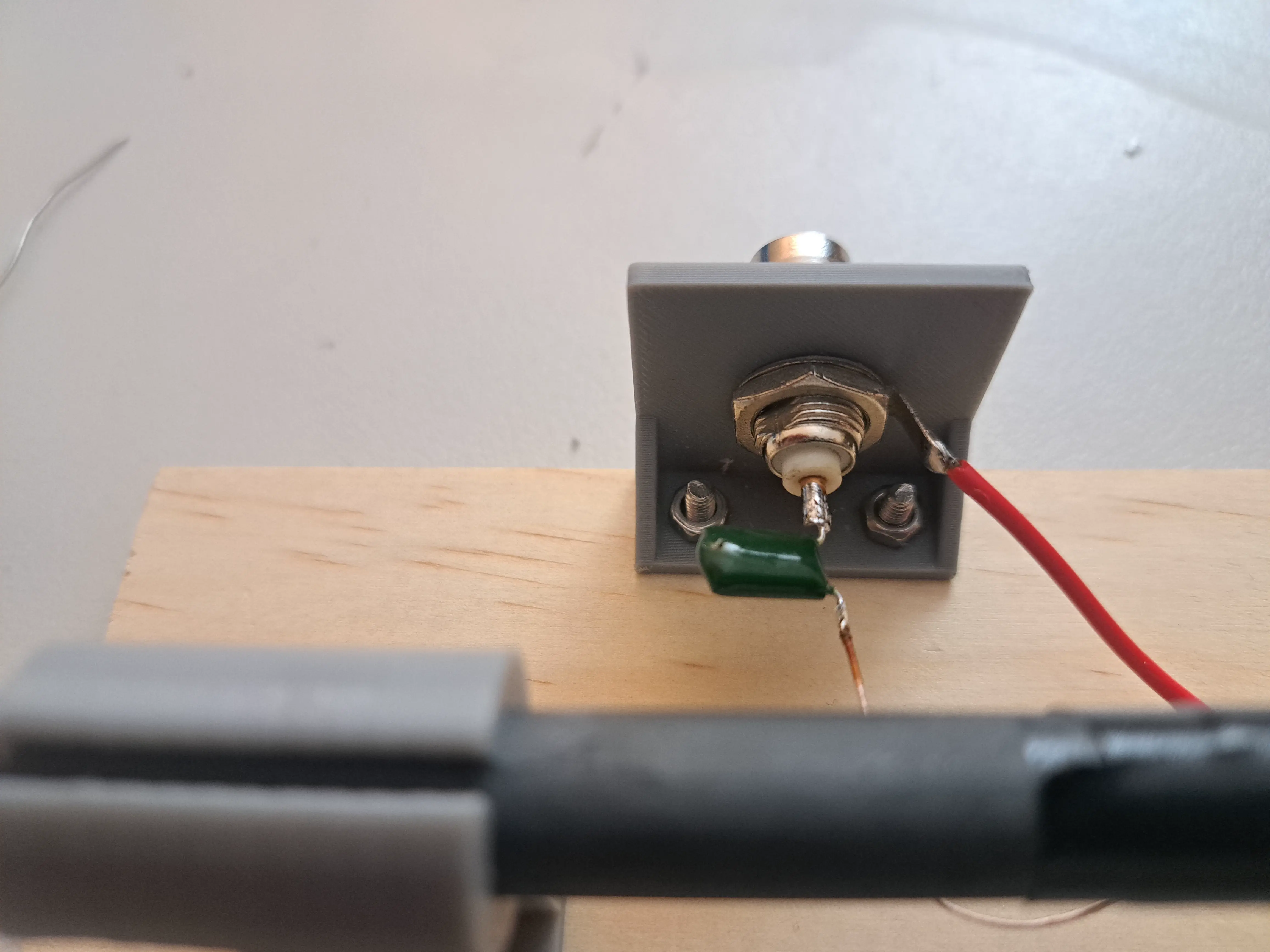
- Mount the BNC connector and solder:
- One end of the coil to the BNC center conductor
- The other end to the BNC ground
Assembly Notes and Safety
This antenna presents a DC short across the RTL-SDR input. This is perfectly safe as long as the Bias-Tee is disabled.
Do not enable Bias-Tee while using this antenna:
- On the RTL-SDR V3, this could damage the Bias-Tee circuitry.
- The V4 includes protection, but enabling Bias-Tee is still not recommended.
To make the antenna safer, insert a 10 nF capacitor in series between the BNC center pin and the antenna winding. This allows RF to pass while blocking DC.
This antenna is highly directional, so you’ll almost certainly want to be able to rotate it to null or peak signals. Keep this in mind when designing the mounting.
Why There’s No Tuning Capacitor
You may notice that I have not included a tuning capacitor in parallel with the loopstick. This is intentional. Rather than creating a resonant AM antenna, I’m using the loopstick as an untuned small magnetic loop antenna, leaving tuning and filtering to the RTL-SDR.
Adding a capacitor would increase signal strength by forming a resonant circuit, but it would also significantly narrow the bandwidth and require manual re-tuning. By keeping the loop untuned, the antenna behaves as a relatively broadband magnetic loop, which works well for SDR use across the AM broadcast band and beyond.
Operation
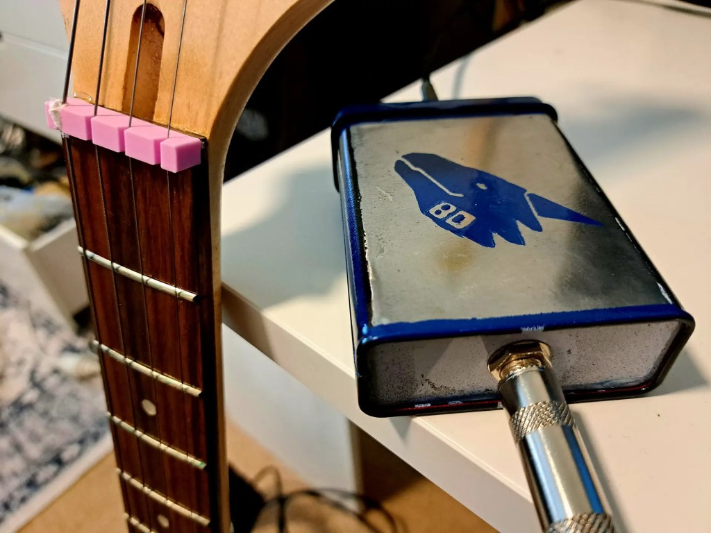
Here’s an example of this antenna in operation, receiving ABC Australia weather on 891kHz
Troubleshooting
The RTL-SDR Blog V3 must be put into direct sampling mode for AM reception with this loop-stick antenna See the user guide for details
On the RTL-SDR Blog V4, direct sampling mode is not required because the V4 includes an HF upconverter front end that lets it tune HF frequencies directly; trying to enable direct sampling on the V4 won’t help and often yields no result.
The type of wire used for the antenna construction isn’t critical. Litz wire or Enameled copper wire is traditional, but light-gauge insulated hook-up wire will also work fine.
Ensure Bias-Tee is disabled. On some RTL-SDR units, enabling Bias-Tee can introduce noise in the AM bands.
This antenna is directional, so try slowly rotating it to maximize signal reception.
Finally, verify that AM stations are actually available in your area — AM broadcasting is limited or absent in some regions.

Leave a comment