
If you’ve ever tried plugging a passive guitar straight into a computer soundcard, you might have noticed that it sort of works… but the signal is low, the tone is flat, and moving your guitar’s controls can sometimes do weird things.
Typical solutions are USB sound interfaces, or dedicated preamps — like the more advanced amplifier I built in this previous post, which uses a modern CMOS op-amp to drive line-level inputs. That circuit works anywhere but, of course, needs a battery.
This new, simpler buffer is different: it doesn’t provide gain or line-level output, so it only works with microphone inputs. But the advantage is that it runs entirely from the small bias voltage already present on your soundcard, no batteries required.
The Problem: Plugging Directly into a Mic Input
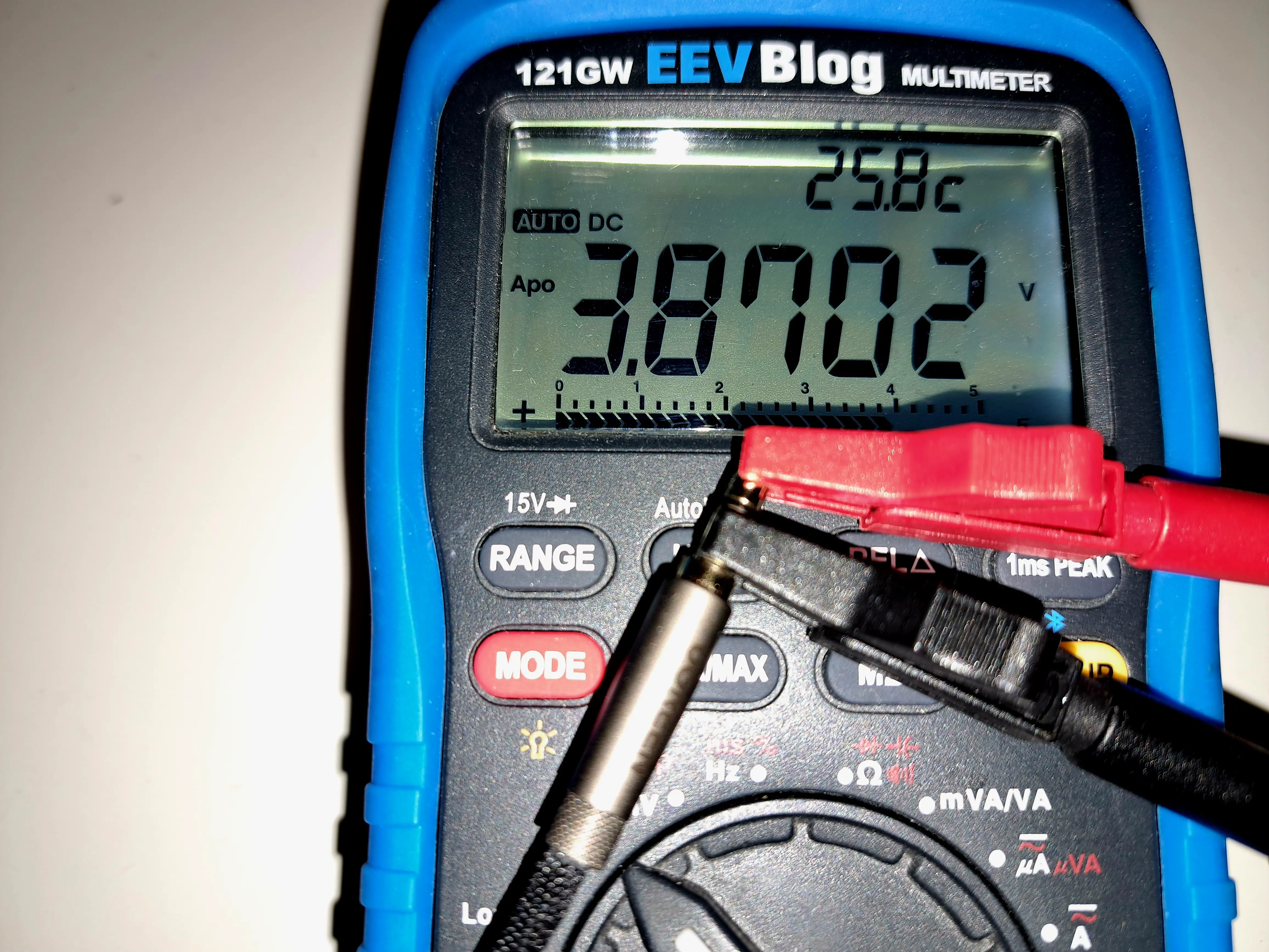
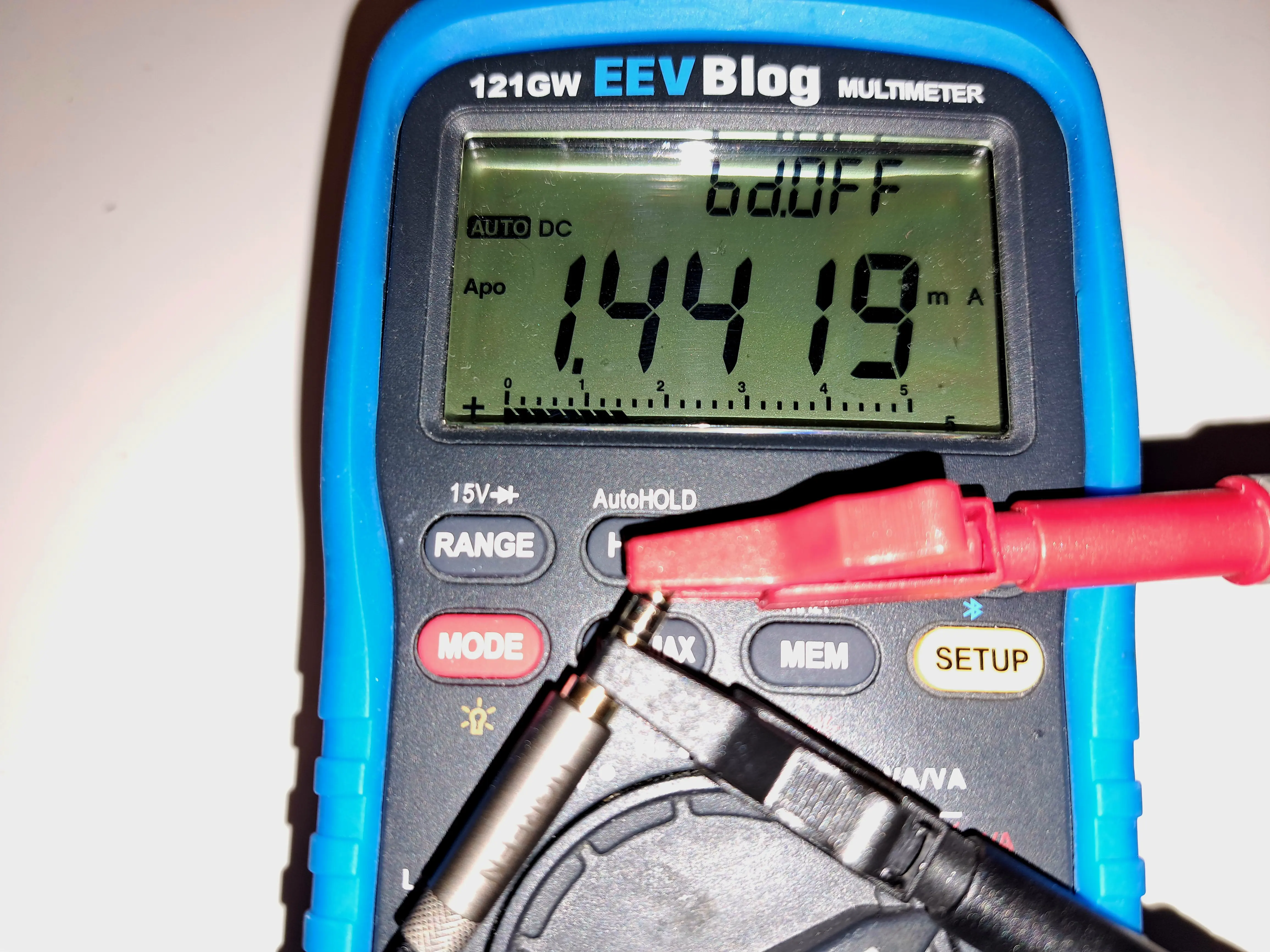
Many consumer soundcards provide a small DC bias voltage on the mic input. This is not phantom power (+48 V), but a tiny voltage (typically 2.5–4 V at 0.5–2 mA) intended to power electret microphones. I’m going to try to leverage it to amplify the current from my guitar.
Before building this project, make sure your sound card provides a DC bias. You can check this by setting your input to microphone and measuring between the sleeve and ring of the input jack with a multimeter. If you read a few volts or more, your sound card should be compatible with this project.
If you plug your guitar straight in, you may run into issues:
Tone degradation
The tone can sound flat, dull, or lifeless. Passive guitar pickups are designed to drive a high-impedance load, but most consumer mic inputs present a much lower impedance — typically 600 Ω to 2 kΩ.
When you plug a guitar directly into such an input, the pickup and input form a voltage divider. Combined with the inductance of the pickups, this creates an RC low-pass filter, rolling off high frequencies and muting the signal. In my testing, the signal was technically usable, but it sounded like the guitar’s tone knob was permanently turned all the way down.
Control weirdness
Your volume knob, pickup selector, or coil-split switches can act unpredictably. Turning the volume knob may produce scratching noises, certain positions may trigger bursts of noise, and switching pickups can cause sudden jumps in volume. This happens because DC from the mic input flows through the guitar’s controls — something they weren’t designed for. It’s also affected by the fact that switching pickups or coils changes the guitar’s output impedance; when connected to the relatively low-impedance mic input, this can cause the signal amplitude to vary unexpectedly.
Even when the tone seems okay, the behavior of your guitar can be unstable — which makes recording or playing through software frustrating.
The Solution: A Simple JFET Buffer
A tiny JFET stage fixes all of these problems. It:
- Blocks DC from reaching the guitar, so controls behave normally
- Presents a high impedance to the pickups, preserving tone
- Outputs a low-impedance signal that the mic input can handle
- Runs entirely off the mic bias voltage, no batteries needed
The result? The guitar sounds exactly like it’s supposed to, the tone comes alive, and the controls work predictably.
Parts you’ll need
- 2N5457 JFET (AliExpress | Amazon )
- Assorted Resistors (AliExpress | Amazon)
- 6.5mm Panel Mount Jack (AliExpress | Amazon)
- 3.5mm Panel Mount Jack (AliExpress | Amazon)
You’ll also need either:
Or a
Schematic

Ground should be connected to the mic, guitar, and case
How It Works
This circuit is a JFET buffer, also called a source follower. It doesn’t amplify the voltage of your guitar signal — that stays roughly the same — but it does increase the available current. With more current available, less voltage is lost across the soundard’s microphone input.
High-impedance input for the guitar: The JFET gate draws virtually no current, so your pickups see a very high impedance. In this circuit, the input impedance is set by R2 to about 1 MΩ
Low-impedance output for the soundcard: The signal comes from the JFET source, which is dominated by R3. This gives an output impedance of roughly 3.3 kΩ, low enough for a mic input to handle cleanly without tone loss.
DC blocking: The gate is isolated from both the source and drain, so no DC voltage reaches the guitar.
Even if your soundcard happens to behave well without a buffer, this circuit guarantees consistent tone and control behavior across different devices, thanks to the defined input and output impedances.
Choosing Capacitors for This Circuit
This is a very simple circuit, but capacitor choice matters more than you might expect — especially in a high-impedance audio path like this one.
Ceramic (MLCC) Capacitors
Multilayer ceramic capacitors are small, cheap, and will last forever, but many common types (such as X7R and X5R) are microphonic. In my first build I used a 10 µF X7R capacitor in the signal path (C2). Electrically it worked fine, but the circuit is microphonic — tapping the enclosure produced clearly audible noise.
Verdict: Avoid X7R/X5R ceramics in the signal path. (C0G/NP0 types are fine electrically, but usually not available in large enough values.)
Liquid Electrolytic Capacitors
Standard electrolytics are easy to find and generally behave well in audio circuits. They are not microphonic, but they do have two downsides:
- They must be installed with the correct polarity
- Over very long periods (many years), they can dry out
If you use an electrolytic capacitor, choose a sensible voltage rating and double-check the polarity. The soundcard’s mic input sits at a higher DC voltage due to its bias supply, so the positive terminal of the capacitor should be connected on the soundcard side.
Verdict: Perfectly acceptable and beginner-friendly if used correctly.
Tantalum Capacitors
On paper, tantalums look like a good fit: compact, stable, and available in useful values. In practice, they performed poorly in this circuit. The leakage current was high enough to disturb the bias point, pulling it toward ground and preventing the JFET from biasing correctly.
Tantalums are also extremely sensitive to polarity — even a brief reverse-voltage event can permanently damage them and increase leakage.
Verdict: Not recommended for this project.
Solid Aluminum (Polymer) Capacitors
Solid aluminum polymer capacitors should also work very well here. They are:
- Non-microphonic
- Very low leakage
- Long-lived
- Happy at low voltages
While I didn’t use one in my own build, their electrical characteristics make them an excellent choice for this application.
They’re less likely to be lying around in a junk box, but if you have them, they’re ideal. If you’re buying new parts specifically for this project, this is the type to get.
Verdict: Best choice if available.
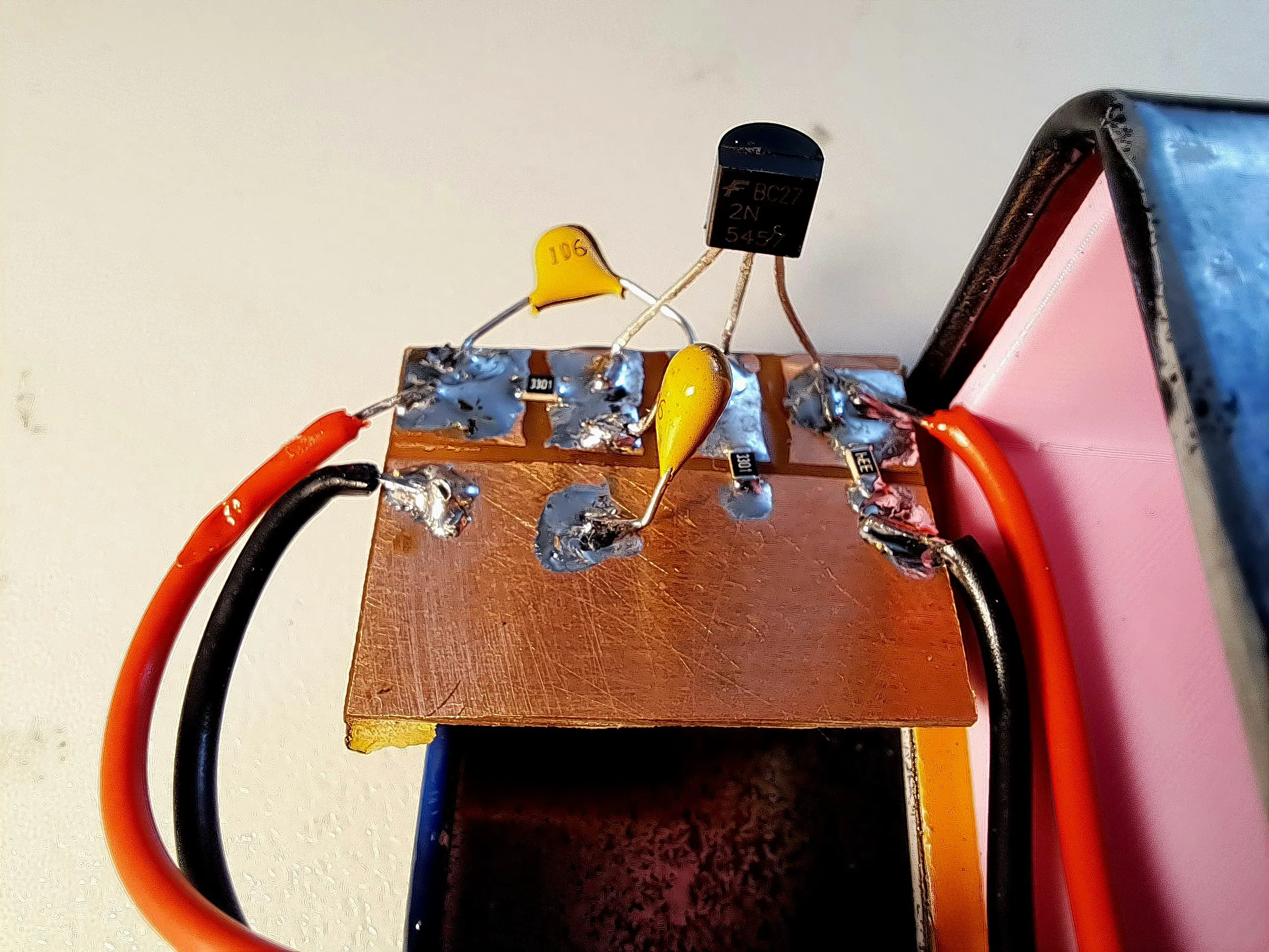
Construction
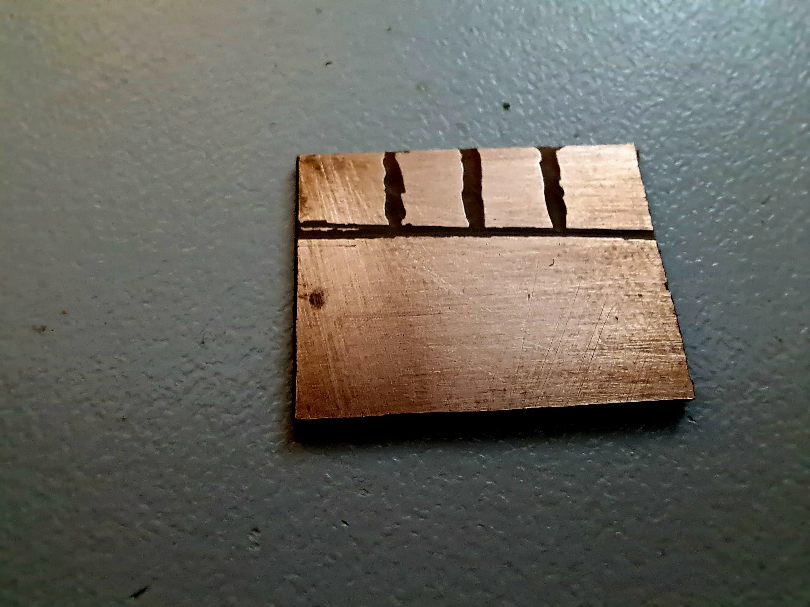
Due to the simplicity of the circuit, I decided to make the PCB by cutting islands into a scrap piece of bare board. This circuit only has four nodes plus ground, so I could lay them out in a simple two-row grid: four nodes along the top for the circuit, and a single row along the bottom dedicated entirely to ground.
Note: When building this circuit, it’s likely simpler to connect the tip and ring (L and R) of the microphone together, this increases the available bias current, and means you don’t need to deal with separating channels when recording.
Enclosure
Because this circuit presents a high-impedance input, it can pick up tiny currents from ambient noise. For that reason, a metal case is practically mandatory.
Make sure the circuit has a good electrical connection to the case, and if possible, the panel-mount audio connectors should also make solid contact with the enclosure. This helps shield the circuit from interference and keeps your recordings clean.
I used a small metal tin from a local discount store — originally intended for cigarettes. I sanded off the original decoration and gave it a fresh coat of spray paint to make it look nicer. Simple, cheap, and effective.
Results
Here’s a sample recorded directly from the buffer using my Realtek onboard soundcard. I’m very happy with the results: the noise is low, and the tone is clear and bright.
Please forgive my amateur playing — I’m just a beginner! The point here is the circuit, not my chops, and it shows that even a simple, battery-free JFET buffer can deliver a clean, usable guitar signal.
As an added bonus, turning up the guitar’s volume can slightly overdrive the buffer, producing a warm, tube-like overdrive.
It’s subtle and gives a bit of vintage character, without harshness or extreme fuzziness.
Here’s a quick recording:
Post your build photos or questions below!
FAQ
Q: Should I put a 10 kΩ or 20 kΩ resistor in series with the gate to protect against ESD and static shock?
A: Yes — that’s a great idea. The resistor helps limit current into the gate and dissipates the energy from a static discharge, protecting your JFET from damage.
Q: There’s a lot of noise when I use this. What can I do?
A: Try lowering the input resistor R1 to 500 kΩ or 330 kΩ. This may slightly reduce the treble, but it should dramatically lower noise. Experiment to find the best balance between tone and noise for your setup.
Q: Can I use a different JFET?
A: Yes. Many small-signal JFETs marketed for microphone preamps will work fine. Just make sure it’s a typical low-noise N-channel JFET.
Q: I only get audio out of one channel.
A: Try soldering the tip and ring (left and right) of the connector together. This will feed the buffer output to both channels and give you a mono signal on stereo inputs.
Q: How do I make sure that the circuit does not draw more current than the audio interface can safely provide?
A: There’s no risk of damaging your sound card. The internal bias resistor in the soundcard limits the current to a tiny value, so the sound card remains safe—even if there were a dead short present.
In my testing with various onboard Realteks, USB sound cards, and Intel audio, all provided about 3–4 V at 1 mA on the mic input, which is more than enough for this circuit.
If you have a multimeter, you can test your sound card to confirm it can supply at least 0.5 mA.
Normally, the circuit draws only about 0.3–0.4 mA, since it presents a DC impedance of over 6.6 kΩ. This is well within the limits of a typical sound card mic input, so in most cases, you don’t need to worry.
If there is a problem, you might notice clipping or very low gain. You could double all resistor values to reduce current, but increasing them too much can make the JFET operate poorly and cause distortion, meaning the circuit might not function on some sound cards.
Because the circuit is cheap and quick to build, the simplest approach is just to try it.


Leave a comment