
In the early days of metal detecting, a simple type of detector known as a BFO (Beat Frequency Oscillator) was commonly used. While it does not perform as well as more modern designs, it is quick and easy to build, and may still be good enough for beachcombing for coins or rings.
A traditional BFO detector consists of two inductor–capacitor (LC) oscillators. The first oscillator uses the search coil as its inductor. The second oscillator uses a separate inductor and is tuned to the same frequency as the first. These are commonly referred to as the search and reference oscillators.
The audio output of a BFO detector is produced by taking the difference between the frequencies of the search and reference oscillators. When no metal is near the search coil, both oscillators run at the same frequency, so the difference is zero and no sound is heard.
When a piece of metal is brought near the search coil, its inductance changes, which in turn shifts the resonant frequency of the search oscillator. The frequency difference between the two oscillators is no longer zero—perhaps 300 Hz, for example—resulting in an audible tone.
In this design, instead of using a traditional reference oscillator, an Arduino is used to measure the frequency of the search oscillator. When the Arduino detects a change in frequency, it can activate an LED or a buzzer to indicate that a metal object has been detected.
Parts you’ll need
- Assorted Resistors (AliExpress | Amazon)
- Assorted Polyester Film Capacitors (AliExpress)
- 0.5mm Magnet Wire (AliExpress | Amazon)
- Arduino Nano (AliExpress | Amazon)
- Assorted Transistors (AliExpress | Amazon)
And you may also need:
Schematic

This circuit is a simple Colpitts oscillator with the resonant circuit comprised of C2, C3 and SEARCH_COIL. This oscillator will have a frequency of approximately 260khz. ( Colpitts calculator )
The peak amplitude of this oscillator can be too high for the Arduino to measure, and if we connected it directly, would cause damage to the micro-controller. Zener diode D1 is used to limit the voltage on the Arduino pin to a safe 4.3V. C5 and R4 ensures the output of the oscillator is referenced to ground.
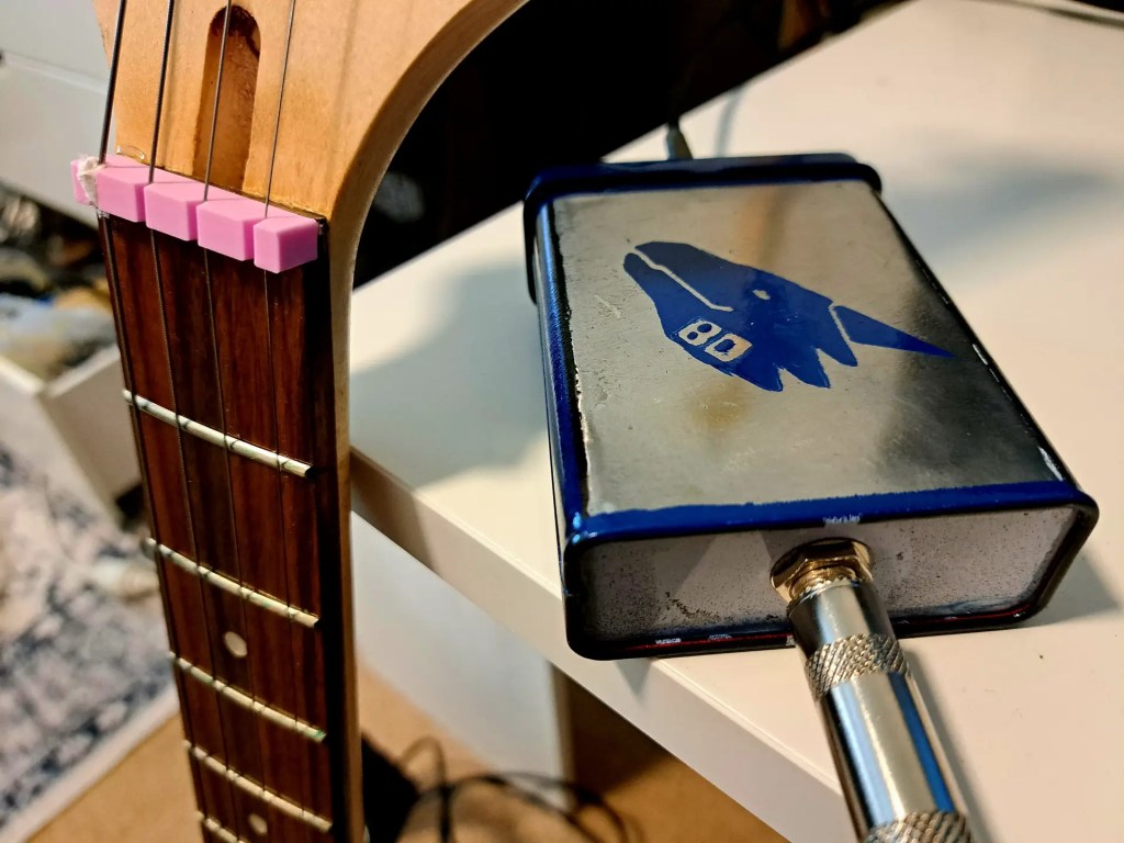
The Search Coil
Any coil with an inductance of around 200–400 µH should work, and you should aim to keep the resistance as low as possible.
This inductance range will produce an oscillation frequency of roughly 200–400 kHz, which is within the range the Arduino can reliably measure.
Keep in mind that larger coils are better at detecting larger objects at greater depths, while smaller coils are more sensitive to small items such as coins, rings, and similar targets.
You can use this table as a guide to construct your coil:
| Size | Shape | Turns | Wire size | Inductance | Resistance |
|---|---|---|---|---|---|
| Ø 120 mm | Round | 36 | Ø 0.40 mm / 0.14 mm2 | 405 µH | 1.9 Ohm |
| Ø 150 mm | Round | 31 | Ø 0.40 mm / 0.14 mm2 | 394 µH | 2.0 Ohm |
| Ø 175 mm | Round | 28 | Ø 0.40 mm / 0.14 mm2 | 387 µH | 2.1 Ohm |
| Ø 200 mm | Round | 26 | Ø 0.40 mm / 0.14 mm2 | 406 µH | 2.2 Ohm |
| Ø 250 mm | Round | 22 | Ø 0.40 mm / 0.14 mm2 | 380 µH | 2.3 Ohm |
| Ø 300 mm | Round | 20 | Ø 0.50 mm / 0.20 mm2 | 390 µH | 1.6 Ohm |
| Ø 400 mm | Round | 17 | Ø 0.50 mm / 0.20 mm2 | 396 µH | 1.8 Ohm |
| Ø 500 mm | Round | 15 | Ø 0.50 mm / 0.20 mm2 | 400 µH | 2.0 Ohm |
| 1.0 x 1.0 m | Square | 10 | Ø 0.66 mm / 0.34 mm2 | 406 µH | 2.0 Ohm |
| 1.4 x 1.4 m | Square | 8 | Ø 0.66 mm / 0.34 mm2 | 387 µH | 2.2 Ohm |
| 1.8 x 1.8 m | Square | 7 | Ø 0.80 mm / 0.50 mm2 | 398 µH | 1.7 Ohm |
Code
At a high level, the code in this design performs the following steps:
At startup:
- Count the number of pulses occurring over a 100 ms interval.
- Store this value as the baseline frequency.
In the main loop:
- Count the number of pulses occurring over a 100 ms interval and store this value as count.
- If count differs from the baseline, turn on an LED to indicate a detection.
To compensate for slow changes in environmental conditions, the baseline is gradually adjusted in the main loop:
- If count is greater than the baseline, increment the baseline.
- If count is less than the baseline, decrement the baseline.
Fortunately, the FreqCount library can be used to measure the number of pulses within a fixed time interval, keeping the rest of the code relatively simple.
You can download the source code for this project.
Results
The completed detector demonstrates the core principles of BFO metal detection using a very simple circuit and minimal components. Its straightforward design makes it quick to build and easy to experiment with, allowing results to be obtained with relatively little setup or calibration.
In practice, the detector is best suited to light-duty tasks where ease of construction and responsiveness are more important than absolute performance. Potential uses include beachcombing, locating studs, or detecting cables and pipes behind drywall.
The following video shows the detector in operation.
FAQ and Troubleshooting
Oscillator Voltage
If you have access to an oscilloscope, it is worth checking the voltage at the collector of the transistor. You should see a reasonably clean sine wave with a peak-to-peak voltage of roughly 1.5× the supply voltage.
If the voltage is too high, the waveform may become clipped. In this case, slightly reduce the capacitance of C1 to lower the oscillator gain.
If the voltage is too low, increase the capacitance of C1 slightly to raise the gain.
Arduino Pins
The Arduino pins that can be used to measure frequency depend on the specific board. This project was built using an Arduino Nano; for other boards, consult the FreqCount library documentation to determine which pins support frequency measurement.
Arduino Input Voltage
For the Arduino to reliably count pulses from the search oscillator, the voltage at the input pin must swing above and below approximately 3 V.
If the input voltage is too low, you can slightly increase the capacitance of C5 or the resistance of R4. Conversely, if too much current is flowing through the protection Zener diode D1, reducing C5 can help limit the current.

Leave a reply to Jan Aarden Cancel reply