
In this article I’ll show you how to set up and start developing with the CH32V003 — an ultra-low-cost RISC-V microcontroller — including choosing hardware, setting up tools, and writing your first code
The CH32V003 family
For anyone who hasn’t played with it yet, the CH32V003 family is shockingly capable for the price. In practice: comparing it to an Arduino Nano (ATmega328P) almost feels unfair. The CH32 runs at a blistering 48 MHz—three times the Nano’s 16 MHz—while still offering the same 2 kB of RAM and conceding only half the flash memory (16 kB vs. 32 kB). But don’t let that make you think it’s a minor upgrade—it’s a 32-bit RISC-V microcontroller, not an 8-bit AVR. That means a modern instruction set and more efficient processing.
And the price? Absolutely ridiculous. At around $0.25 per chip, it significantly outperforms comparable Atmel parts that still cost $2.00 or more.
Sure, it has fewer GPIO pins (18 vs. 23) but the CH32V003 integrates a single-channel DMA controller, 10-bit ADC, op-amp/comparator, multiple timers, and standard buses (USART, I2C, SPI). Operates on 5V or 3.3V, and there’s a single-wire debug/program interface.
And here’s the kicker: it has a built-in op-amp. That tiny addition makes it ideal for sensing and analog-heavy projects—something you won’t find on an ATmega or ATtiny at this price point.
Honestly, comparing it to an ATmega328P is being generous. A fairer fight is with the ATtiny series, and in that matchup the CH32V003 wins outright: faster, more ram, better debugging, and more capable.
In short, the CH32V003 isn’t just cheap—it’s smart, fast, and flexible, a microcontroller that punches far above its cost and leaves its 8-bit competition looking a little embarrassed.
The CH32V003 comes in several hobbyist friendly packages that are compact and easy to solder;
| Part Number | Package | Pin Count | Notes |
|---|---|---|---|
| CH32V003J4M6 | SOP-8 | 8 | Easy to solder, minimal peripherals |
| CH32V003A4M6 | SOP-16 | 16 | Easy to solder. Most peripherals except SPI |
| CH32V003F4P6 | TSSOP-20 | 20 | Trickier to solder (smaller pitch). All peripherals. |
Each of these variants has exactly the same clock speed, RAM and flash memory, but of course they differ in the available peripherals and GPIO
Note: The CH32V003A4M6 does not have a functional SPI interface due to the absence of an SCK pin. If your project requires SPI, the CH32V003F4P6 is the recommended choice.
Parts You’ll Need
💡 Which board should you choose?
- Pre-made board: Fastest to get started, includes extras like a USB connector. (Note: The CH32V003 does not support USB; these boards use USB for power only)
- DIY PCB: Most cost-effective (~$0.30/board), minimal design, good grounding, pin labels, direct access to programming pins.
- DIP adapter: Budget-friendly and reusable. It works, but lacks a ground plane and requires installing the decoupling capacitor on the breadboard with long traces. No pin labels—you’ll need the datasheet handy.
Everyone needs a programmer:
If you want to DIY a PCB or use a DIP adapter, you’ll want the microcontroller, these are available from the manufacturer’s official AliExpress store:
⚠️ Chip Selection Update (January 2026):
The pin-compatible CH32V006F8P6 (8KB RAM, 62KB Flash, 7 DMA, 12-bit ADC (upgraded from 10-bit) is now available direct from WCH’s official AliExpress store at the same price as the CH32V003F4P6 used in this tutorial (~$0.26/chip).
While I haven’t personally tested the V006 yet, it’s pin compatible and supported by PlatformIO so it should work identically with this tutorial. Unless you specifically need the V003, the V006 is likely the better choice for new projects.
And perhaps some supporting passives:
If you intend to breadboard, you’ll also need an TSSOP to DIP adapter:
Or alternatively:

My PCB is V-scored to fit 15 snap-off dev boards per PCB.
So when ordered via JLPCB, you end up with 5*15 = 75 PCBs for $3.50. Or a price of $0.046 each. In combination with the bulk pricing from the WCH Store ~$0.24 per micro-controller. That’s 30 cents each! Can’t be beaten!
You can download the entire EasyEDA project here if you wish to modify it.
If you don’t want to DIY a dev board. You can also buy a:
- Pre-made CH32V003F4P6 board (AliExpress | Amazon)
- Pre-made CH32V006F8P6 boards don’t seem common yet (At least not cheaply)
Schematic

The schematic is very straight-forward. The only truly critical component is the C1 decoupling capacitor. It must be placed as close to the chip’s pins as possible and have a solid ground connection. That’s difficult to achieve on a breadboard, which is where the dev board becomes especially useful.
To program the chip, you only need to connect GND and SWIO to the corresponding pins on the programmer — just two wires at minimum. If you’re powering the chip from the programmer, you’ll also need to connect VCC.
I’ve included a few optional conveniences that you can omit if desired:
- A de-bounced reset switch
- An LED on GPIO PD3
Programmer
The CH32V003 series is programmed using the proprietary WCH-LinkE programmer. This is a low-cost, single-wire programming interface that also supports single-wire debugging (SWD). The official programmer additionally includes a USB-to-TTL serial interface, which can be used to monitor debug output.
When you first plug in the programmer, you’ll probably see that there are missing drivers in device manager.
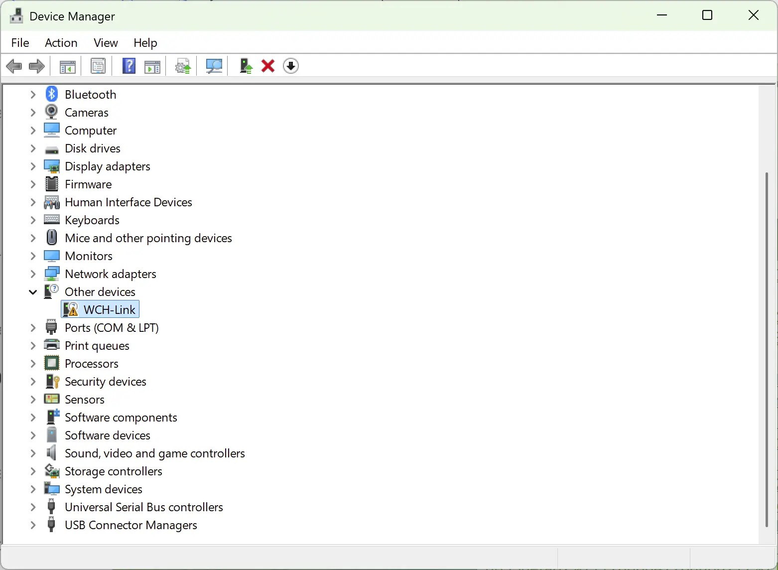
- Download the driver from GitHub https://github.com/Community-PIO-CH32V/wchlink-driver-windows/archive/refs/heads/main.zip
- Install the driver in the folder WCHLink and WCHLinkSER. These are the drivers for the programmer, and the programmer’s inbuilt TTL-USB serial device
- Check device manager and expand both “Ports (COM & LPT)” and “Interface” in the tree. You should see that both the WCH-LINK SERIAL and the WCH-LINKRV devices are present.

Once you see both drivers are working correctly, you can move onto the next step.
Set RISC-V mode.
The programmer supports both an ARM and a RISC-V mode. If the programmer is in ARM mode, there you will see a blue LED lit. If there is no blue led, you can ignore the rest of this and go straight to setting up the programming environment.
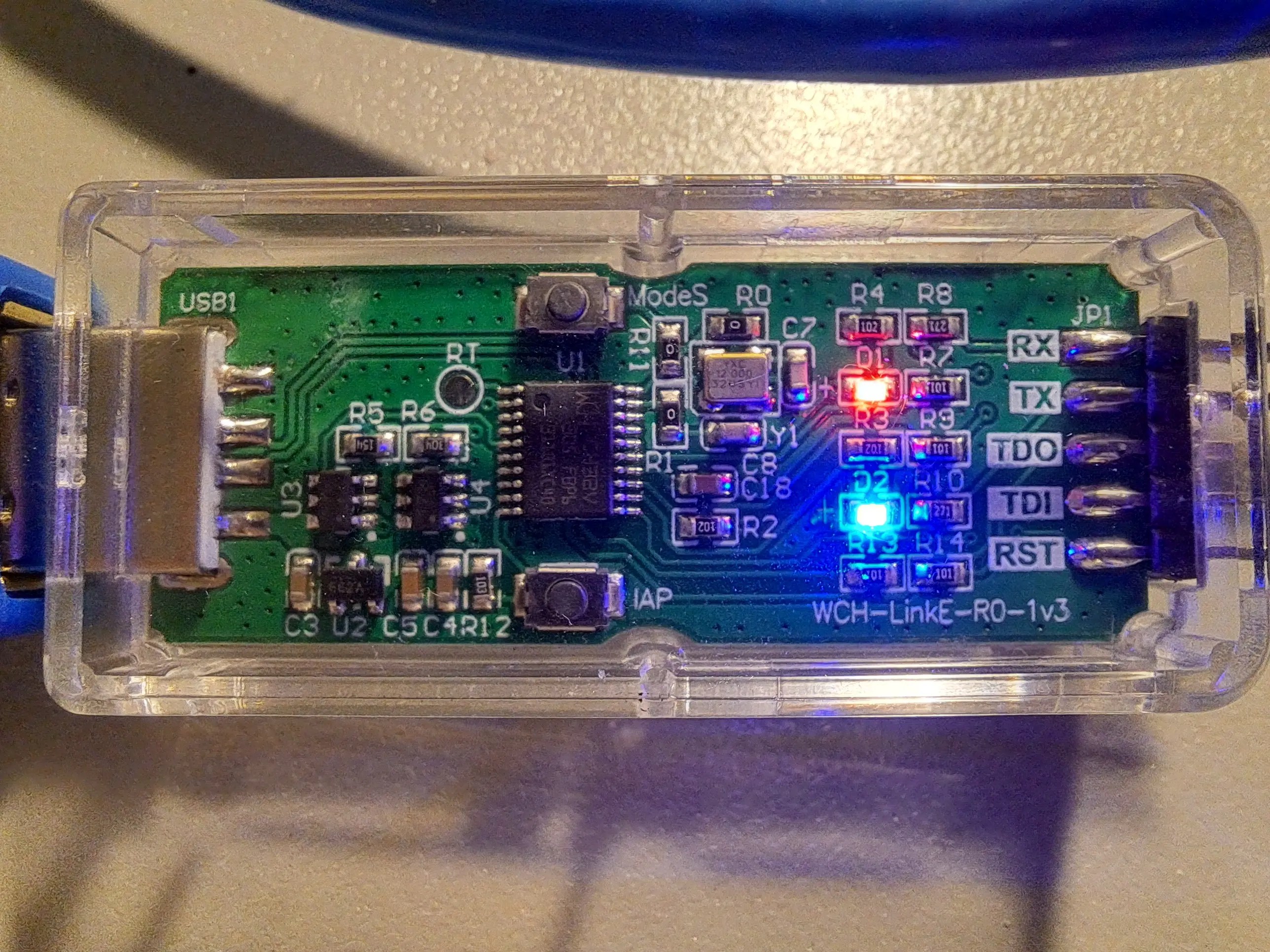
If the blue LED is lit, you have to swap the mode. Luckily, you only have to perform this step once, as the mode will be written to eeprom.
There are three options I’m aware of to set the mode:
- Hold down the ModeS button while you plug the programmer into your USB port (Case can be a bit tricky to open though)
- Download the WchLinkUtility https://www.wch.cn/downloads/wch-linkutility_zip.html
- Use the python rvmode.py utility
I went with the WCHLinkUtility. Unzip and run WCHLinkUtility and then:
- Press Refresh
- Select WCH-LinkRV in the “Active WCH-Mode:” drop down
- Press Set

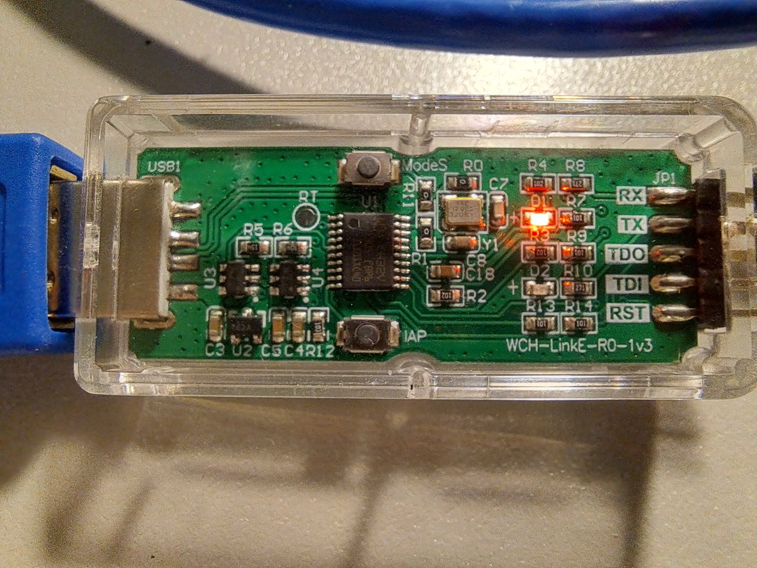
The blue led should no longer be lit, indicating the programmer is in the RISC-V mode. You can go onto the next step.
Connect the Programmer
Due to the SWD (Single-Wire-Debug) programming support. Only three wires are needed, and all are connected directly to the corresponding pins.
| Microcontroller | Programmer |
|---|---|
| SWIO | SWIO |
| VCC | VCC |
| GND | GND |
| RST (Optional) | RST (Optional) |
The programming wiring is so simple, it’s almost not worth this table.
Programming Environment
This setup is for the PlatformIO environment and the VSCode editor. There are options for Arduino IDE. But the PlatformIO solution is more mature, and debugging is supported out of the box!
Install PlatformIO Extension
- Open VSCode Extension Manager
- Search for official PlatformIO IDE extension
- Install PlatformIO IDE.
- Restart VSCode

Add WCH32 support
Support for the WCH32 isn’t currently included by default with PlatformIO. This support needs to be added
- Select the PlatformIO icon (Ant head icon on the left)
- Select Quick Access -> PIO Home -> Platforms
- Select Advanced Installation

Next, paste in the following URI
https://github.com/Community-PIO-CH32V/platform-ch32v.git
Press Install. If successful, you’ll be greeted with something like:

Create a new WCH32 project
Create a new project
- Select the PlatformIO icon (Ant head icon on the left)
- Select Quick Access -> Open -> New Project

In the new Project Wizard
- Enter a name ‘ch32-blink’
- Select board Generic CH32V003F4P6(W.CH)
- Select the Ch32v003fun framework
- Click finish

Ch32fun is a lightweight, bare-metal development framework for WCH’s line of microcontrollers. Ch32fun takes a minimalist approach—it gives you just the essentials (headers, tooling, and a single-file library) so you can work directly with the hardware registers as described in the chip’s Technical Reference Manual.
Add Code
1. Create a new file /src/funconfig.h
Add the following contents:
_FUNCONFIG_H _FUNCONFIG_H// Place configuration items here, you can see a full list in ch32fun/ch32fun.h// To reconfigure to a different processor, update TARGET_MCU in the Makefilefunconfig.h is a per-project configuration header file that you create to customize how the ch32fun framework behaves for your specific application. It’s automatically included by ch32fun.h and serves as the main way to configure various system settings before the framework initializes.
We don’t need to configure anything now, but common settings you’d define in funconfig.h include:
- FUNCONF_SYSTEM_CORE_CLOCK – Sets the target CPU clock speed (e.g., 48MHz for CH32V003)
- FUNCONF_USE_DEBUGPRINTF – Enables fast printf debugging over the programming interface
- FUNCONF_USE_UARTPRINTF – Enables printf over UART instead
- FUNCONF_UART_PRINTF_BAUD – Sets UART baud rate (typically 115200)
- FUNCONF_SYSTICK_USE_HCLK – Configures whether SysTick runs at full CPU speed or divided
- CH32V003 (or CH32V203, etc.) – Defines which specific chip you’re targeting
- FUNCONF_USE_CLK_SEC – Enables the clock security system
- FUNCONF_DEBUGPRINTF_TIMEOUT – Sets timeout for debug printf operations
2. Create a new file /src/main.cpp
Add the following contents:
"ch32fun.h" <stdio.h>// use defines to make more meaningful names for our GPIO pins PIN_LED PD3int main(){ SystemInit(); funGpioInitAll(); // Enable GPIOs funPinMode(PIN_LED, GPIO_Speed_10MHz | GPIO_CNF_OUT_PP); // Set PIN_1 to output while (1) { funDigitalWrite(PIN_LED, FUN_HIGH); Delay_Ms(1000); funDigitalWrite(PIN_LED, FUN_LOW); Delay_Ms(1000); }}Remember to adjust the PIN_LED define for your board.
Upload
Click the upload button in the bottom right — you can also use the items in the Quick Access under Platform IO

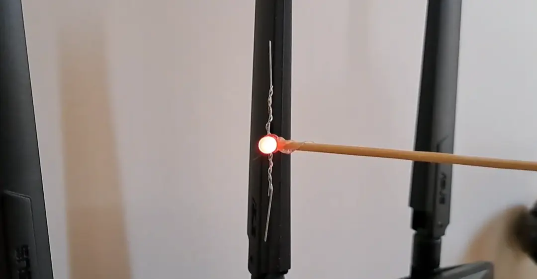
If everything worked you should see a green [SUCCESS] message and your LED will begin blinking.
Debugging
One of the most pleasant surprises about this chip is its fully featured debugging interface, supported over the same single-wire connection used for programming.
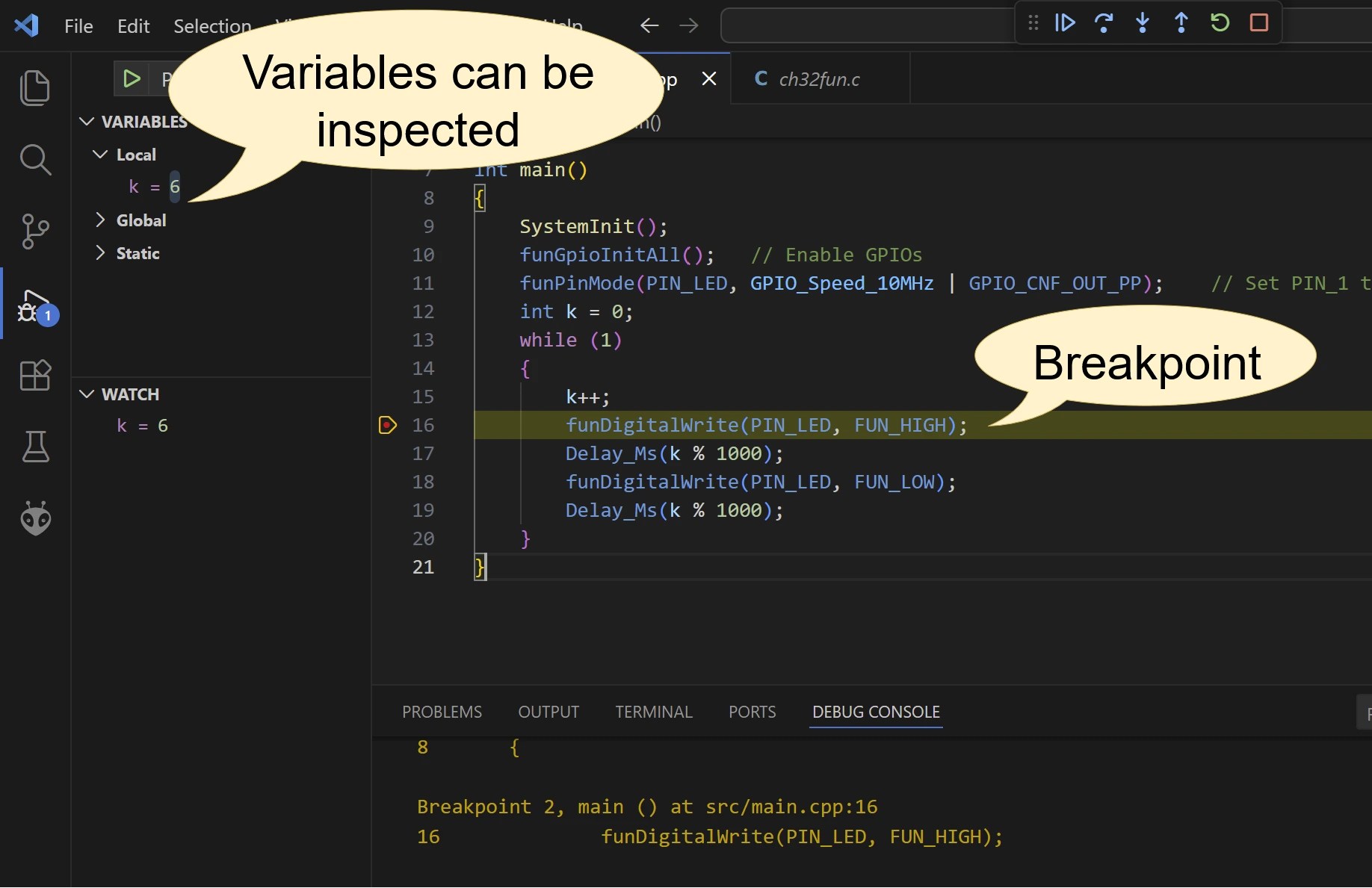
No additional setup is required to debug your project in real time. Simply set a breakpoint and click the menu item Run → Start Debugging.
A breakpoint will be hit at the very beginning of the project—ignore this and press continue. Your breakpoint should be hit next.
That’s it, congrats, you’re done!
Next Steps
For the next steps, I suggest checking out the examples included with the ch32fun framework. There examples demonstrate how to perform most common tasks on the CH32.
I also suggest reading the reference manual


Leave a Reply