
Like most dangerous activities, playing with high voltage is a lot of fun. Sadly, I only have access to a measly 30V from my lab PSU. How can I go from this pitiful voltage up to a more substantive tens-of-thousands of volts one may ask?
Well, one of the easiest way is to make use of one of these:
This odd-looking device is a flyback-transformer, you can find them in old CRT TVs and computer monitors. If you don’t want to dirty your dainty little paws with dumpster diving you can also buy new ones on ebay for about $15. These fly-back transformers convert pulses of current into high voltage dc.
I’m going to use a trusty 555 timer oscillator to generate square pulses. We’ll need pulses of a frequency of around 10 to 50khz to make the fly-back transformer work. I’m going to aim at the lower end of this to help the circuit run cooler. I’ll amplify the pulses using a mosfet; it’s likely that a mosfet will run cooler in this application — mosfets tend to be better in applications where a transistor will spend a lot of its time either completely turned on, or completely turned off.
Here is the schematic for a 555 based fly-back driver:

Everything in this circuit to the left of R3 is just a simple 555 square-wave generator. I used an online calculator to come up with reasonable values. While experimenting, I found that having a duty-cycle of around 90% resulted in longer sparks, so R1 is much larger than R2 in this circuit. You might also want to consider replacing R1 and R2 with potentiometers in this circuit so you can tune the frequency and duty cycle to get the best result.
This is what the output from the 555 timer (U1) in the above circuit looks like:
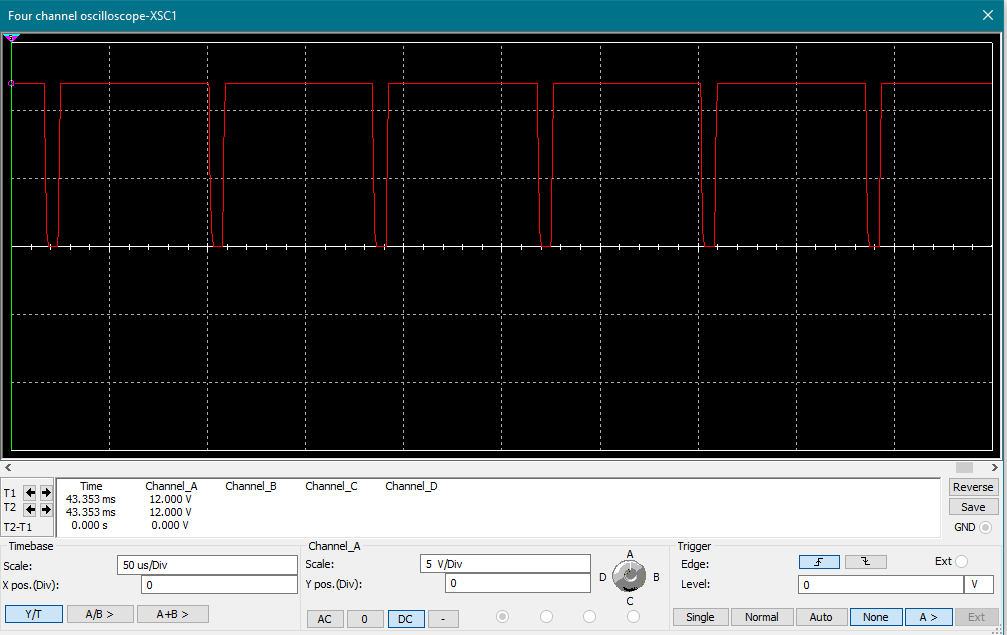
Q1 and Q2 in this circuit form a push-pull buffer, the goal of this buffer is to ensure the mosfet turns on and off at a good clip. Mosfets tend to have fairly high gate capacitance which needs to be overcome to switch them quickly. Q1 is responsible for rapidly charging the mosfet gate, and Q2 for discharging it. It would have been simpler to use a mosfet gate-driver IC here instead (Such as the TC427) but I didn’t have any handy. The mosfet (Q3) t gets a little warm, in this circuit; you’ll need to slap a small heatsink on there to keep it happy.
Here is the completed circuit constructed on strip-board:
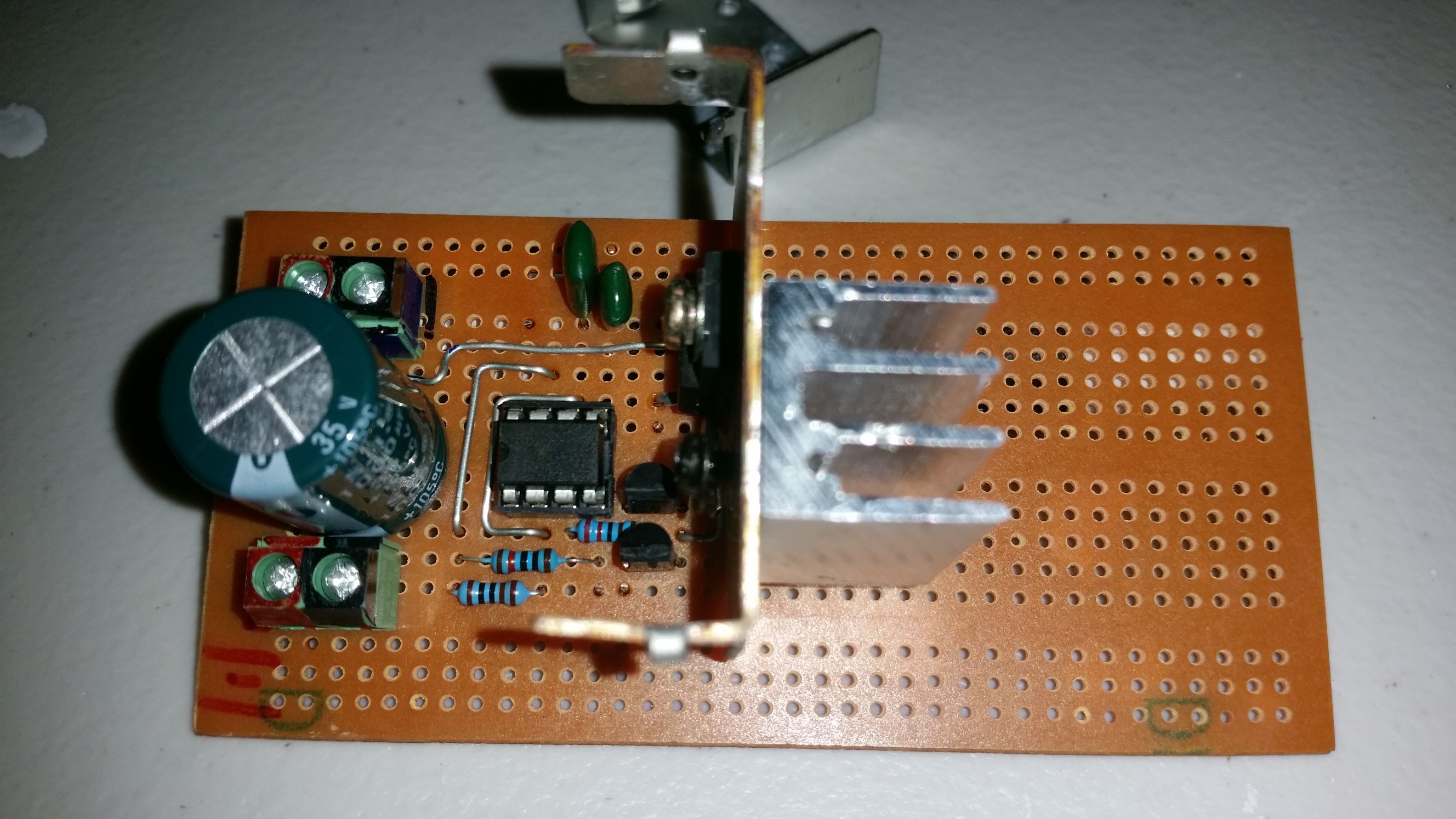
Before you can get started, you’ll have to work out which pins the primary winding on your transformer is connected to I’ve found that the primary winding is almost always has a resistance of, or very nearly, 0.8 ohms, so try measuring every combination of pins on your transformer, then try each pair with the right resistance until you see sparks.
The output from the secondary is of course easy to find, because it’s the big red wire coming out the top. To find the ground for the secondary however, just wave the output wire near the unused pins, the arcs will jump to the ground pin to show you which it is!
With the circuit now built, and the windings on the transformer now identified, it’s finally time to play with some sparks!
Hopefully I’ll come up with some more high voltage experiments using this generator in the future.
Have fun!

Leave a comment