
I was looking for an adjustable oscillator to use as a frequency source for my Tesla coil. From previous testing, I already knew the coil resonated at approximately 2 MHz, since I had built a Slayer-exciter circuit earlier and measured its operating frequency.
A common first choice for a simple oscillator is the 555 timer. However, when I built a 555-based oscillator, I found that 2 MHz was slightly beyond the practical operating range of the standard device. Faster CMOS 555 variants are available, but I didn’t have any in the lab at the time.
As an alternative, I considered using an astable multivibrator:
The multivibrator would certainly be fast enough. However, adjusting its frequency requires changing both R1 and R2 simultaneously, which is inconvenient without a double-ganged potentiometer. I didn’t have one available. In addition, the basic circuit does not produce very sharp edges unless several extra diodes are added. Overall, it felt like unnecessary complexity just to generate an adjustable square wave.
What You’ll Need
SN74AC14N (AliExpress | Amazon | LCSC)
Resistors Kit (AliExpress | Amazon)
A Schmitt Inverter To The Rescue
A common oscillator used in digital applications is the circuit shown below:

This looks promising because it can generate a square wave using only three components, and the frequency can be adjusted by varying a single resistor. You can find a detailed explanation of how this oscillator works here:
http://electronics-course.com/schmitt-trigger-oscillator
There’s an informative video about these type of oscillators here:
I built the circuit using a Texas Instruments SN74AC14N, which I happened to have left over from a previous project. The SN74AC14N is particularly well suited to this application because of its very short switching time—on the order of 1.5 to 11 nanoseconds. As a result, it can produce a square wave with very sharp edges, even at my target frequency of 2 MHz.
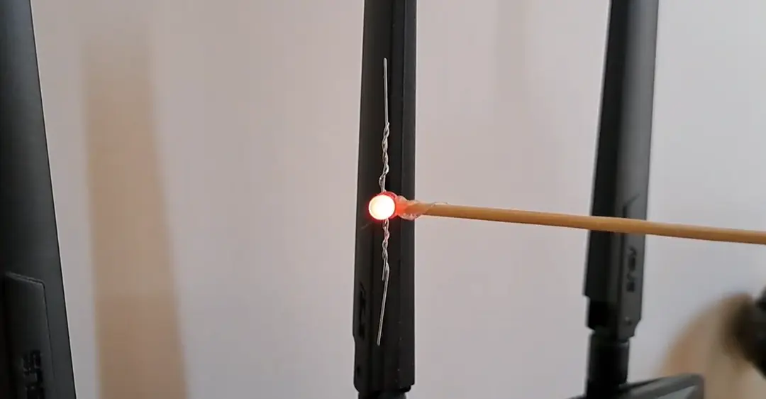
The video above shows the oscillator being tuned over a wide frequency range by adjusting (R1), which I’m quite happy with. The circuit produces clean square waves across a broad range of frequencies. I was able to run it up to about 4–5 MHz, as shown, and down to roughly 0.3 Hz—slow enough to blink an LED.
Another advantage of this approach is that the SN74AC14N contains six inverters in a single package, allowing you to build up to six oscillators if desired, or to repurpose the remaining gates for other functions. The SN74AC14N is also an inexpensive part, costing around 60 cents from RS Components.
Buffer
Because drawing current from the oscillator can affect its frequency, it is good practice to use one of the remaining inverters to buffer the output, as shown in the circuit below.

Using inverter A2 at the output of A1 prevents the load from affecting the oscillator formed by A1.
Frequency
To calculate values for a target frequency use the calculator here. Enter your operating voltage and desired frequency, select whether to solve for R or C, input the known component value, and press calculate to find the unknown value.
Typical values for R range from about 2.2 kΩ through to 100 kΩ while typical values for C range from 1nF through to 10μF.
Issues
I encountered a problem where the oscillator would not start reliably on power-up. One commonly suggested fix is to add a relatively large resistor (around 50 kΩ) in series with the timing capacitor. This helps pull the inverter input toward ground at startup, forcing the output high and kick-starting the oscillation. However, in my case, this approach did not resolve the issue.
The solution that completely eliminated the problem was to run the oscillator from a 3.3 V supply instead of 5 V. This worked well for my application and resulted in reliable startup behavior.
Have fun!


Leave a Reply