
I’ve accumulated quite a few inductor cores over time—some scavenged from old equipment, others bought from online retailers. Unfortunately, many of them no longer have accessible datasheets. To better understand what these cores might be useful for, I decided to measure their saturation current.
Core Saturation
Every magnetic material has a limit to how much magnetic flux it can support. As current through the coil increases, the magnetic field inside the core becomes stronger, causing the magnetic domains within the material to gradually align with the applied field.
Once most of these domains are aligned, the material can no longer significantly increase its magnetization and additional current produces only a small increase in magnetic flux.
As a result, the inductor begins to behave more like an air-core coil and the effective permeability of the core drops sharply.
This has a direct effect on the inductance. The inductance of a coil depends on the permeability of the core material according to the standard inductance equation:
Inductance Formula
- L – inductance (henries)
- μ – permeability of the core material
- N – number of turns in the coil
- A – cross-sectional area of the core (m²)
- l – magnetic path length through the core (m)
Because inductance is proportional to permeability, any reduction in permeability causes the inductance to increase. Since inductance determines how strongly a component resists changes in current, a drop in inductance allows the current through the inductor to rise more rapidly.
This rapid rise is exactly what I’m expecting to see on the oscilloscope trace and I’ll use it to detect when a core begins to saturate.
What You’ll Need
Resistors Kit (AliExpress | Amazon)
Polyester Film Capacitors Kit (AliExpress | Amazon)
400 Grit Diamond Plate (AliExpress | Amazon)
IRLZ44N MOSFET (AliExpress | Amazon)
MnZn E-Core (AliExpress | Amazon)
22x14x8mm MnZn Toroid (AliExpress | Amazon)
1N5822 Schottky Diode (AliExpress | Amazon)
Other:
Consumables. Wick, flux, etc (AliExpress | Amazon)
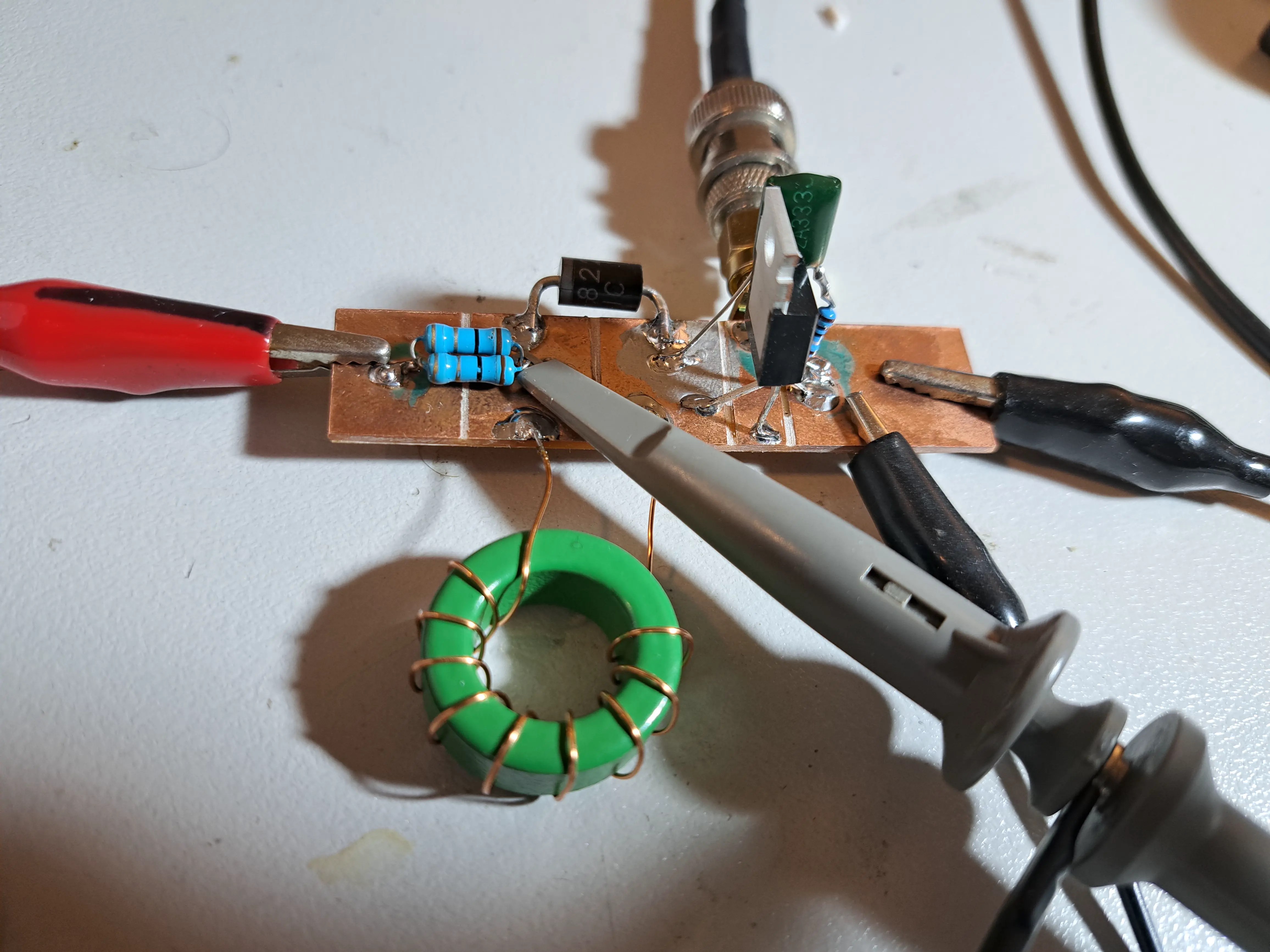
Schematic

The high-level operation of this circuit is fairly straightforward. A voltage is applied to the gate of Q1, turning the transistor on. This applies voltage across L1, causing the current to increase while Q1 remains on — limited only by the series resistance and the maximum current that V1 can supply.
If the inductor were ideal, the current would rise along a smooth, straight slope. In reality, the core will eventually saturate, causing the slope of the current ramp to decrease. By monitoring the current through RSense, we can clearly see this deviation from the ideal slope, allowing us to detect the onset of saturation.
For the current shunt, I used two 1 Ω resistors in parallel to create a 0.5 Ω sense resistor. Using additional resistors in parallel (for example three or four) would reduce the total resistance further, allowing the same current to be reached with a lower supply voltage.
Care must also be taken to ensure that V1 provides a high enough voltage to reach the inductor’s saturation current, taking into account the total series resistance of RSense, L1, and Q1.
Voltage Spikes
The remaining components in the circuit are included to safely dissipate the energy stored in L1 when Q1 switches off.
D1 is known as a flyback (or freewheeling) diode. It provides a path for the current through L1 to continue flowing when Q1 turns off.
Without D1, the voltage at Q1’s drain would rise dramatically as the magnetic field around L1 collapses. Because the inductor resists sudden changes in current, it will generate whatever voltage is necessary to keep the current flowing. Without a path for that current, this voltage spike could easily exceed the rating of Q1 and damage it.
Keep in mind that D1 must be a Schottky or ultra-fast diode, as slower diodes may have insufficient reverse-recovery speed, allowing a voltage spike to appear at the drain of Q1.
Even with D1 in place, there can still be some parasitic inductance in the power supply wiring that lies outside the current path provided by the diode. This stray inductance can still generate voltage spikes when Q1 turns off.
Although it is probably not strictly necessary, I added a snubber circuit across Q1 to provide additional protection while testing various inductors. The snubber consists of C1 and R1, connected in parallel with the MOSFET.
This network helps absorb any remaining voltage spikes and dissipate the associated energy, reducing the risk of damaging Q1 during testing.
Pulse In
For this circuit to work, you need to provide a trigger pulse to the gate of Q1. (PulseIn) The duration of this pulse will depend on the inductor and the supply voltage:
- Longer pulses are required for inductors with higher inductance
- Shorter pulses should be used when the input voltage is higher
The pulse duration required to reach saturation depends on the rate of current rise in the inductor, which is determined by the applied voltage and inductance according to:
The pulse frequency and duration should also be kept relatively low to prevent excessive heating in the inductor and other components.
I used a signal generator to create the pulse, but there’s no reason you couldn’t use a microcontroller such as an Arduino.
The pulse parameters I used were:
- Voltage: 10 V
- Duration: 2 milliseconds
- Frequency: 10 Hz
Measurements
MnZn Toroid Core
I first measured a small MnZn toroidal core, the same one that I used in the joule thief.
It has the following parameters:
- Number of turns: 10
- Inductance: 274 μH

The purple line on the chart represents the expected behavior of an ideal inductor. The point where the measured waveform begins to deviate from this line indicates the onset of core saturation, which in this case occurs at approximately 0.4 A, around 25 µs into the pulse.
Large E core
Here I repeat the test using a large ferrite E-core. This core has many more turns, resulting in higher inductance, so it takes longer for the current to rise for a given voltage — the additional inductance resists changes in current.
It’s important to remember that increasing the number of turns increases the magnetic flux generated for a given current, which can cause the core to reach saturation at a lower current. At the same time, larger cores contain more magnetic domains, which allows them to handle higher currents before saturating.
Even though this core is physically much larger, the large number of turns means we expect it to saturate at a current only slightly higher than that of the smaller core.
It has the following parameters:
- Number of turns: 50
- Inductance: 5.00 mH


This core began saturating at around 0.4 A and exhibits a relatively sharp saturation point. Notice that the current slope for this inductor is much lower than before — with higher inductance, the current ramps up more slowly. It took approximately 0.6 ms for this core to reach saturation, compared with only 25 µs for the previous one.
Gapped E-Core
Because I have more of these E-cores than I need, I thought it would be interesting to experiment with manually adding an air gap.
There are two main ways to increase the saturation current of an inductor: reduce the number of turns, or add an air gap to the magnetic core.
Reducing the number of turns is often not ideal because inductance scales with the square of the number of turns, while the magnetic flux (and therefore saturation) scales linearly with the number of turns. This means that if you halve the number of turns, the inductance drops to a quarter of its original value, while the saturation current only doubles.
Adding an air gap reduces the effective permeability of the magnetic path. As the gap increases, the inductance decreases roughly linearly with the gap length, while the saturation current increases roughly linearly as well. This is advantageous compared to reducing the number of turns which reduces it by square.
Relationship of inductance, number of turns, and gap
An interesting fact about gapped inductors is that nearly all of the magnetic energy ends up stored in the tiny air gap rather than in the magnetic material itself. The ferrite core still shapes the magnetic field and provides a low-reluctance path, but the air gap dominates the total magnetic reluctance of the circuit. You can think of the air gap as acting like a stiff spring, the bigger the gap, the larger, and stronger the spring.
The Experiment
I used a small 400-grit diamond plate to remove approximately 0.2 mm from the E-core to create a small air gap. Although this seems like a tiny amount of material, even a small gap can significantly reduce the effective permeability of the magnetic path, and therefore the inductance.


I then returned the bobbin to the core and measured the inductance both with and without the air gap.
| Core Condition | Inductance (mH) |
|---|---|
| Not Gapped | 5.00 |
| Gapped | 1.00 |
As expected, introducing even a small air gap significantly reduced the inductance. Because the inductance decreased by a factor of five, and the ungapped core saturated at around 0.4 A, we would expect the gapped core to saturate at approximately 5 × 0.4 = 2 A.
Next, I’ll repeat the test using the gapped core and examine the results.

There is a clear increase in the saturation current of the gapped core. This core begins to saturate at around 2.4 A, which is slightly higher than the estimated 2 A. In this case, the trade-off between reduced inductance and increased saturation current turned out to be very favorable.
The astute reader may notice that this core saturated in about the same 0.6–0.7 ms as the non-gapped core. That’s because the gap reduces the inductance, allowing the current to rise faster, even though the core can now handle a higher saturation current.
Reducing turns instead?
If, instead of adding a gap, we tried to increase the saturation current from 0.4A to ~2 A by reducing turns, we would have had to remove roughly 4/5 of the turns, leaving only 10 turns remaining. With 10 turns, the inductance would drop to roughly 1/25th of the original (since ), giving an inductance of only about 0.2 mH instead of the 1.0 mH achieved with the gap. So the gapped core allowed us to achieve a much higher saturation point for a given inductance.
Why Core Saturation Matters
Core saturation is a practical problem in many circuits, especially in power electronics. When a magnetic core saturates, the inductor loses its ability to resist changes in current. The inductance drops sharply, meaning that for a given voltage, the current rises much faster than expected. This can lead to several problems:
- Excessive current through components – MOSFETs, diodes, or other switching elements may see currents far above their rated limits, potentially causing overheating or damage.
- Reduced energy storage – Inductors store energy in their magnetic fields. Once saturated, they can no longer store energy efficiently, which can disrupt the intended operation of the circuit.
- Instability in switching converters – In circuits like boost converters, saturation can be particularly harmful. The inductor is supposed to ramp current predictably during the switch-on phase. If it saturates, the current rises uncontrollably, possibly causing voltage overshoot at the output, increased ripple, or even failure of the switching transistor.
Knowing the saturation current of a core allows you to design your circuits robustly. You can:
- Choose a core that will handle the maximum expected current without saturating.
- Decide whether to add an air gap to raise the saturation current.
- Avoid overdesigning or underdesigning your inductor, which can impact size, efficiency, and cost.
Understanding core saturation is essential for reliable, efficient, and safe inductor design, particularly in switching power supplies and converters.


Leave a Reply