
With this project I intend to design and construct a simple AM radio that does not require any esoteric or vintage components and is accessible to the largest possible audience.
One of the simplest types of radio is a tuned radio frequency receiver (or TRF receiver). It is composed of one or more tuned radio frequency (RF) amplifier stages followed by a detector (demodulator) circuit to extract the audio signal and usually an audio frequency amplifier. This type of receiver was popular in the 1920s
If you just want to see it in action, jump to the demonstration.
I came up with a short list of goals for the project
- Minimize total cost
- Minimize the number of unique components
- Use components that are easy to source
- Keep construction simple
- Avoid the need for an outdoor antenna
- Avoid requiring a ground connection
- Provide acceptable audio quality
- Work with standard earbuds
- Runs on a single AA battery
What You’ll Need
Manganese Zinc (MnZn) Ferrite Rod (AliExpress | Amazon) for below 2 MHz
Resistors Kit (AliExpress | Amazon)
Polyester Film Capacitors Kit (AliExpress | Amazon)
Electrolytic Capacitors Kit (AliExpress | Amazon)
Antenna
Traditional crystal radios need a long wire antenna and a solid ground connection—neither of which is easy to arrange if you’re working in a small space or can’t run a wire outside. Thirty metres of hookup wire also isn’t cheap, typically running $15–$25.
A ferrite rod solves both problems. It can act as the antenna, and its higher inductance per turn means the coil needs far less wire to achieve the same result. The rod itself costs under $2, keeping the whole build compact and inexpensive.
Tuning
In addition to acting as a compact antenna, the ferrite rod also allows us to tune the radio by sliding it in and out of the coil.
The resonant frequency of an LC circuit depends on both the inductance (L) and capacitance (C).
Most vintage radios use a variable air-dielectric capacitor for tuning, but these tend to be expensive.
Polyvaricons are a more modern, lower-cost alternative, but their tuning range is usually insufficient to cover the entire AM broadcast band.

To put this in perspective:
- A typical modern polyvaricon capacitor varies from about 60 pF to 160 pF, giving a tuning ratio of only ~2.6×. For a single LC stage with a 300 µH coil, this would cover only about 0.72–1.19 MHz—far short of the full AM broadcast band.
- Vintage air-variable capacitors, often used in crystal radios, adjust from roughly 10 pF to 365 pF, giving a massive ratio of ~36×. This is enough to span the entire AM band with one LC stage.


In my design, the ferrite rod achieves a similar effect. With it fully removed, the coil measures about 17 µH, and when fully inserted, about 400 µH—a tuning ratio of ~23×. This gives a large, continuous tuning range without needing expensive or hard-to-find components
Amplification
A traditional crystal radio is a passive device—powered entirely by the energy captured from the radio transmission itself.
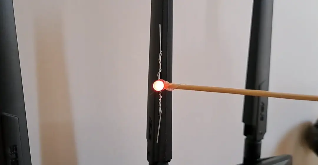
However, without a long-wire antenna and a good ground connection, the radio won’t receive enough signal to function reliably. To address this, the design uses three common bipolar junction transistors to provide amplification.
Amplification provides an added benefit: it allows the use of standard low-impedance earbuds—the kind you likely already have. Traditional crystal radios, by contrast, require high-impedance crystal headphones, which can cost $8–$15—significantly more than a few dollars for a bag of 50 generic transistors.
The downside is that a power source is required, but only a small one—this circuit operates well from a 1.5 V AA or AAA battery. It draws just 1–2 mA, so battery life is excellent.
Demodulation/Detection
Decoding an AM signal into something you can hear is called demodulation; an older term is detection.
In a crystal set radio, a diode typically performs this function. However, a transistor’s base–emitter junction behaves like a diode as well. Since I already have a bag of fifty transistors for this project, I can use an additional transistor to demodulate the signal and convert it into audio, rather than adding a separate component.
Schematic

Tuned Circuit L1 and C1
L1 and C1 form a tuned circuit that selects the desired station. The resonant frequency can be adjusted by varying C1, L1, or both.
The selected frequency is determined by:
For this radio. L1 is variable, and leaving C1 is a fixed 0.33 nF film capacitor.
The lowest value of L1 with the rod fully removed is 19 μH, and the highest value when the rod fully inserted is 409 μH:


This gives a tuning range of:
The AM broadcast band is 540–1600 kHz, so this tuner comfortably covers that range with a little to spare on each side of the ‘dial’.
Transistor Q1
Q1 is responsible for amplifying the tiny current from the tuned circuit. It’s biased into a configuration known as an emitter follower (or common collector) amplifier. This configuration increases the current of a signal, but not the voltage.
At first, it might seem odd to amplify only the current. In an ideal world, both voltage and current would be amplified. However, when signals are extremely weak or at high frequency, transistors can struggle to provide voltage gain.
The emitter follower is well suited to this situation. It presents a high input impedance to the tuned circuit, avoiding loading it down, while providing enough current gain to drive the next stage.
The amplified signal appears at the emitter, ready to be coupled to the next stage via C3.
Transistor Q2
Q2 is configured as a common‑emitter amplifier—the workhorse of small‑signal amplification. Its job is to increase the voltage of the radio frequency signal after Q1 has already boosted the current.
The tuned circuit produces a very weak signal: the voltage may be measurable, but the available current is extremely small. A common-emitter stage requires some base current to operate effectively, and without it, gain is limited.
By placing Q1 in front as a buffer, Q2 receives a stronger, low-impedance signal. This allows it to provide useful voltage gain without loading the tuned circuit.
Resistors R3 and R4 set the bias point for Q2, ensuring it operates in a reasonably linear region. The amplified signal appears at the collector, ready for the final stage.
Transistor Q3
Q3 operates as an infinite impedance detector, combining AM demodulation and audio buffering in a single stage.
Although configured as an emitter follower, the parallel combination of R5 and C4 subtly alters the behavior — the emitter voltage is not an instantaneous copy of the base voltage; instead, it evolves according to the charge and discharge of C4.
Capacitor C4 charges quickly through Q3 when the input signal rises, but discharges much more slowly through R5 when it falls. This causes the emitter voltage to follow the recent peaks of the signal.
Because C4 changes more slowly than the RF signal, the difference between base and emitter depends on whether the instantaneous signal is above or below this stored level, causing the emitter voltage to track the envelope of the AM signal rather than the carrier.
To help clarify this, I’ve created a live simulation that you can view here.

Construction
Antenna
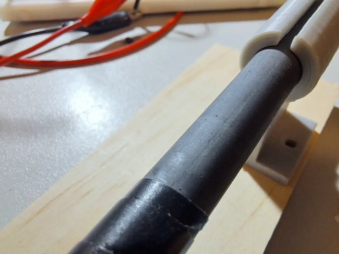
To construct the antenna, start with a tube at least as long as your ferrite rod, and just slightly larger in diameter. This can be a piece of plastic tubing, or if you don’t have one of the right size, a cardboard tube rolled to the appropriate diameter and varnished for strength works well.
Ensure the diameter is wide enough to allow the ferrite rod to slide in and out comfortably. You may also glue a non-conductive stick to act as a handle to the end of the rod to avoid touching it with your fingers, which can shift the tuning.
Wind approximately 100 turns of 0.8 mm enameled copper wire onto the tube. Optionally, you can add a twist or tap every 20 turns. These taps are not required for a basic build, but they give you flexibility to experiment with the antenna, affecting volume and selectivity.
Circuit
The circuit can be assembled on whatever you have available — stripboard, prototype board, breadboard, or even point-to-point wiring using thumbtacks on a wooden board.
To prevent parasitic oscillation, it’s important that the positive side of C6 is connected as close as possible to R3. Keeping this connection short helps maintain stable operation.
For additional experimentation, consider attaching an alligator clip to the end of the C2 connection. This allows you to easily select different taps on the antenna, which can change the volume and selectivity of the radio.


Leave a Reply