
The pulse-width-modulated output of an arduino is often used in conjunction with a small piezo-electric speaker to create tones and music. This simple approach works well; but if you try to scale up this approach and use a larger speaker, you’ll find the power output of the digital IO pin is not sufficient to drive it properly. To drive a speaker loudly, you’ll need to amplify the small amount of power the arduino provides.
Typically the task of amplifying a weak audio signal into a larger one is performed by a linear amplifier. Linear amplifiers have an output that is proportional to (Some multiple of) their input. In one of my previous posts, I built a simple kind kind of linear amplifier. This post, however, I’m going to build an amplifier that operates significantly differently, its output is not a multiple of its input, and so is a non-linear amplifier. This amplifier is also is particularly suited to the arduino as it’s only ever switched completely on, or off. Enter the class D amplifier.
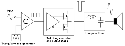
In a class D amplifier the transistors operate as switches — spending all their time either completely turned on, or completely turned off. This means that class D amplifiers can only produce pulse-width-modulated square waves, just like an arduino’s IO pin, only with much higher output current.
Amplifying the signal in this on-off way has several key advantages — the foremost being high efficiency. Current is flowing unimpeded through the amplifier (near zero resistance), or not at all (near infinite resistance), the amplifier is never in an in-between(moderate resistance) state where power is lost as heat. Virtually all power is delivered to the load which is in stark contrast to a normal linear amplifier where much of the power is dissipated as heat by the transistors.
A second advantage is that class D amplifiers don’t suffer from cross-over distortion. Which is a type of error in the output of transistor amplifiers which occurs when the signal ‘crosses over’ the half-way point.
Class D amplifiers have a disadvantage in that you can’t connect the output directly to your speaker. The powerful square-waves produced by the amplifier may even damage your speaker by causing its coils to overheat! We need to convert the output from the amplifier into an analogue signal first. To convert the PWM output of the amplifier into an analogue signal, I’m going to use a low-pass filter known as a Butterworth filter. The low-pass filter averages out high frequencies. If we are to imagine our pulses from the arduino are drops of water of varying size then the filter has an effect similar to a large leaky bucket. If small drops of water fall into the bucket, the water pressure raises slowly, if large drops fall in, the water level raises quickly. This bucket is allowing us to convert different sized rain-drops (different width square-waves), into a pressure (voltage).
Circuit

R1 limits the current to and from the Aduino to 5mA (5V / 1000 ohms).
Q1 and Q2 are configured as a push-pull output stage, they provide the amplification. A small current flowing in or out of the transistor’s bases will allow a much larger current to flow into, or out of, their emitters. Virtually any small PNP and NPN signal transistors will work, so feel free to experiment.
The purpose of C1 in this circuit is to allow only changing currents to flow through it. The idea here is we don’t want current flowing through the speaker when there is no music playing. Any value capacitor from about 100uF upwards will work, larger values may work better if you intend to draw a lot of power out of the amplifier.
L1, L2, C2, C3, C4 form a Butterworth low pass filter circuit. This components convert the pulse-width-modulated digital signal into an analogue output. I used this calculator to determine a reasonable cut-off value for the filter (30khz, well above audio frequencies) and combined with some experimentation arrived at the above inductor and capacitor values.
Results
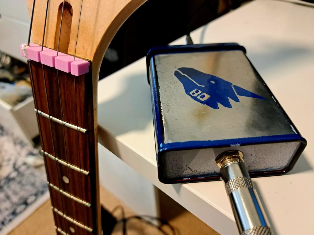
Here is a recording of the arduino and class D amplifier playing 8-bit audio stored on an SD card
If you’d like the source-code that I used to generate the PWM signal for this demo, you can do so here. https://s3.amazonaws.com/siliconjunction/SdPlayerSource.zip
Here is a longer video where I also try my hand at adding some commentary — sorry! I’m still practising!

Leave a comment