
Building a Tesla coil feels almost like a rite of passage—my life didn’t feel quite complete until I built one myself. This project can be frustrating, and I won’t sugarcoat it: you’re likely to blow a few transistors before everything works. Fortunately, I discovered a few tricks along the way that can help save some transistors—and reduce some of the frustration.
Parts You’ll Need
- 0.5mm Magnet Wire (AliExpress | Amazon)
- TIP31C (AliExpress)
- Assorted Resistors (AliExpress | Amazon)
- 1N5819 Schottky Diode (AliExpress)
Step 1 — Winding a secondary
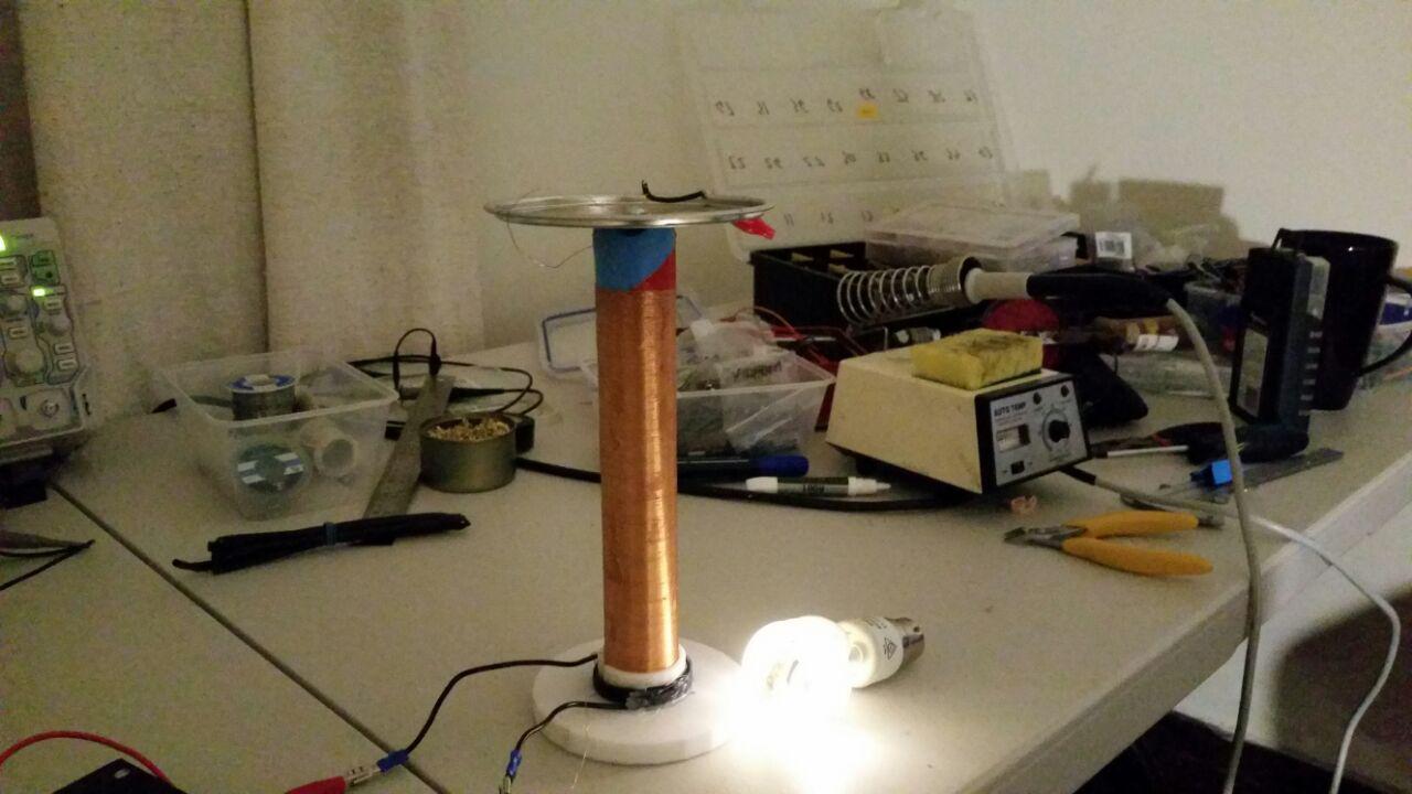
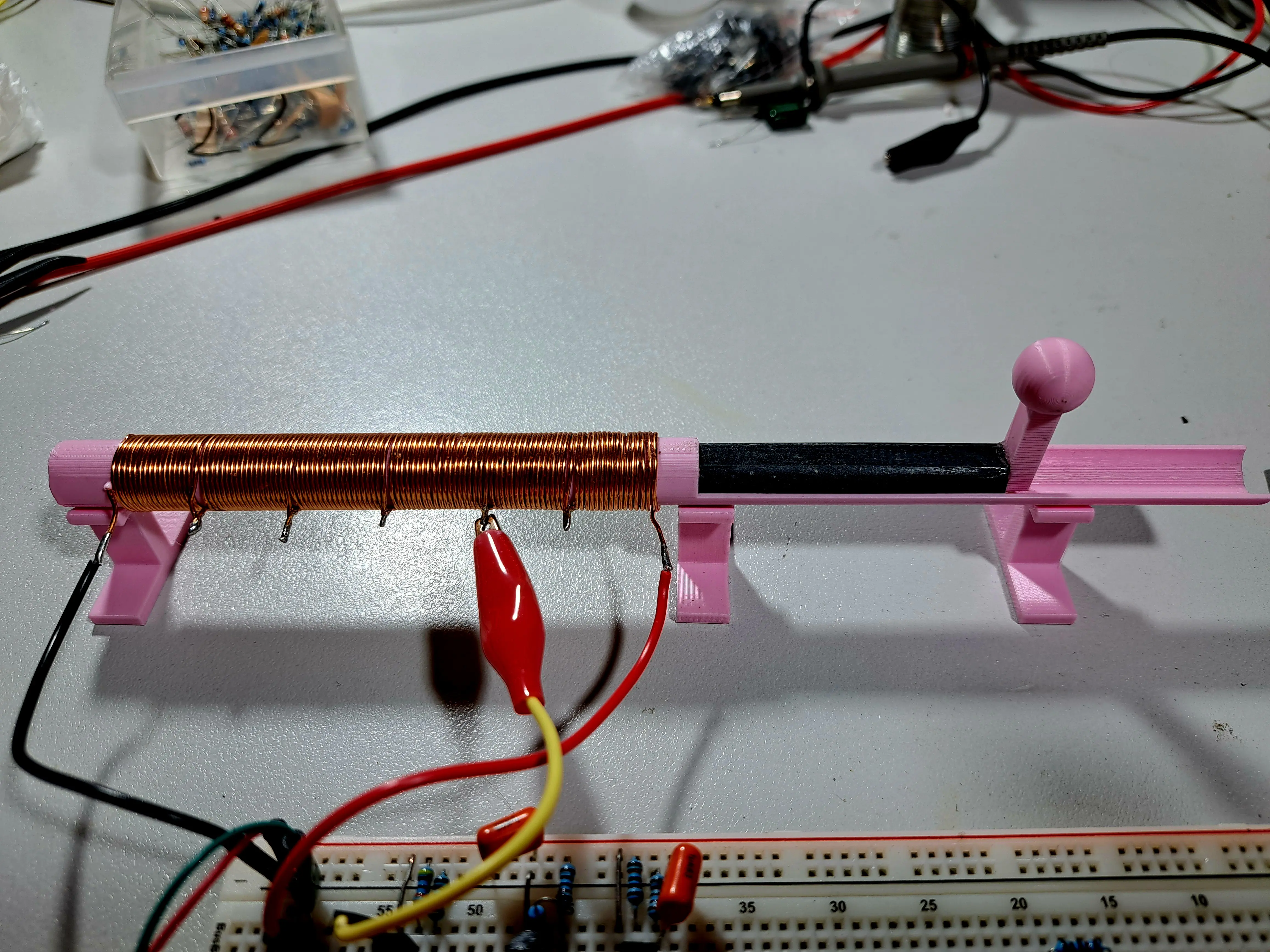
Winding the secondary coil isn’t too difficult. For a small coil, choose a form with a diameter of about 3–8 cm. Aim for roughly 1,000 turns, though a wide range of values will likely work. My coil has around 700 turns and took about an hour to wind while I relaxed in front of the TV.
If you are in need of wire for your Tesla coil, I highly recommend this seller of enameled copper wire for the secondary coil. This enameled copper wire is cheap, easy to solder, has no tangles, and has been handy in my lab for a range of projects!
While winding your coil, it’s a good idea to add a dab of glue or a piece of tape every inch or so to keep the winding from unraveling.
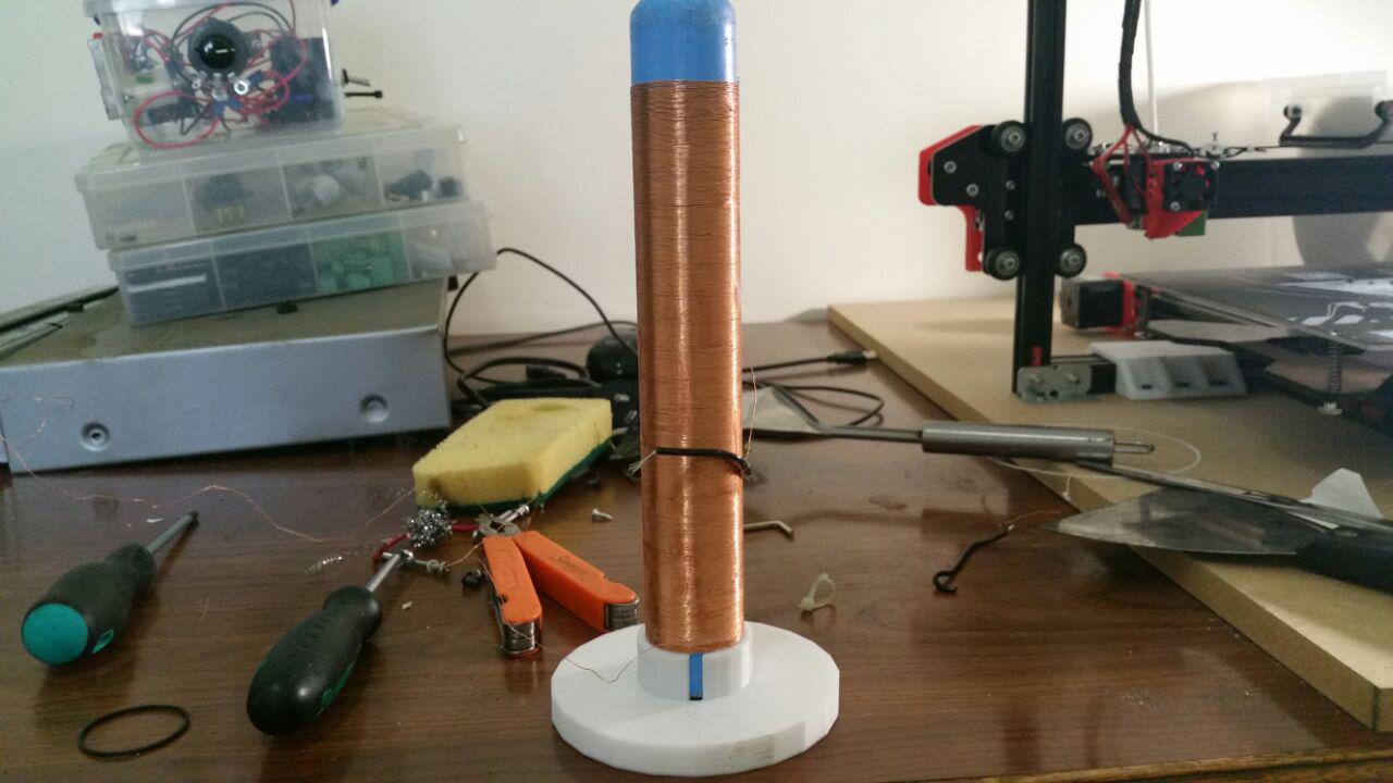
Step 2 — The Primary
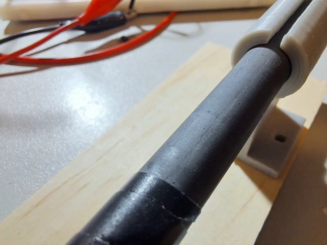
I experimented with several types of primary coils, and the simplest design worked best. I wrapped 5–6 turns of insulated wire around the secondary, a short distance above its base, and secured it with electrical tape.
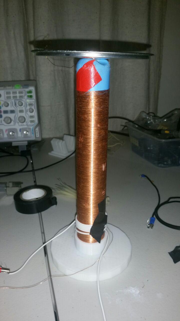
Step 3 — The Top Load
The Tesla coil will still function without a top-load, but adding one lowers the resonant frequency. A lower switching frequency reduces the heat dissipated by your transistor, making it much safer to run. I recommend always using a top-load to minimize the risk of blowing your transistor. For example, without a top-load, my coil’s resonant frequency was about 2 MHz; adding a top-load lowered it to around 1.5 MHz—a significant drop. The top-load can be any disc- or spherical-shaped object; I used a simple coffee-tin lid.
Step 4 — The Driver Circuit
This commonly published slayer exciter circuit is by far the simplest way to get your Tesla coil up and running, you only need one transistor, and one LED to make it work.
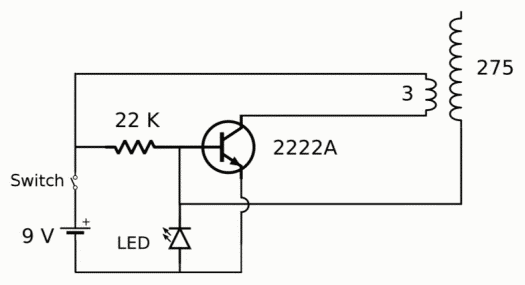
This circuit is delightfully simple—but that simplicity comes at a cost. Crank up the supply voltage, and your transistor can fail suddenly, often without any warning. In fact, this circuit can burn through transistors faster than you might expect. The good news? A few tweaks can make a world of difference for transistor lifespan.
The biggest reliability boost comes from swapping the LED for a Schottky diode. Unlike regular diodes, Schottkys recover from reverse-bias voltage much faster source, which means your transistor only sees those negative base–emitter voltages from the secondary coil for a brief moment—less stress, longer life.
Another smart move is to use a tougher transistor than the 2N2222 and mount it on a decent heat sink. The Slayer Exciter circuit can generate a lot of heat in the transistor due to its slow turn-on and turn-off times, and a stronger, cooled transistor will handle it like a champ.
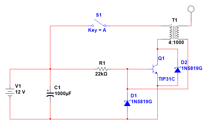
In this improved circuit, the LED has been replaced with a faster Schottky diode, D1. This diode helps prevent the collector–emitter junction of Q1 from being pulled below ground. If the base voltage of Q1 drops below 0 V (for example, to –2 V), current will flow through D1 (held at 0 V) and return the base to 0 V. Such voltage drops can occur due to the inductance of the secondary coil.
D2 is added to protect Q1 from high voltages that may appear on the primary coil. The 1N5819 breaks down at around 40 V, comfortably below the TIP31C’s 100 V rating.
C1 stabilizes oscillations and provides a safe path for the impulses generated by the secondary.
You don’t have to use a 1N5819—any Schottky diode with a breakdown voltage between 20 V and 80 V should work fine.
Finally, remember that this circuit will only operate if current flows through the primary in the correct direction. If your circuit fails to oscillate, try reversing the connections on the primary winding.
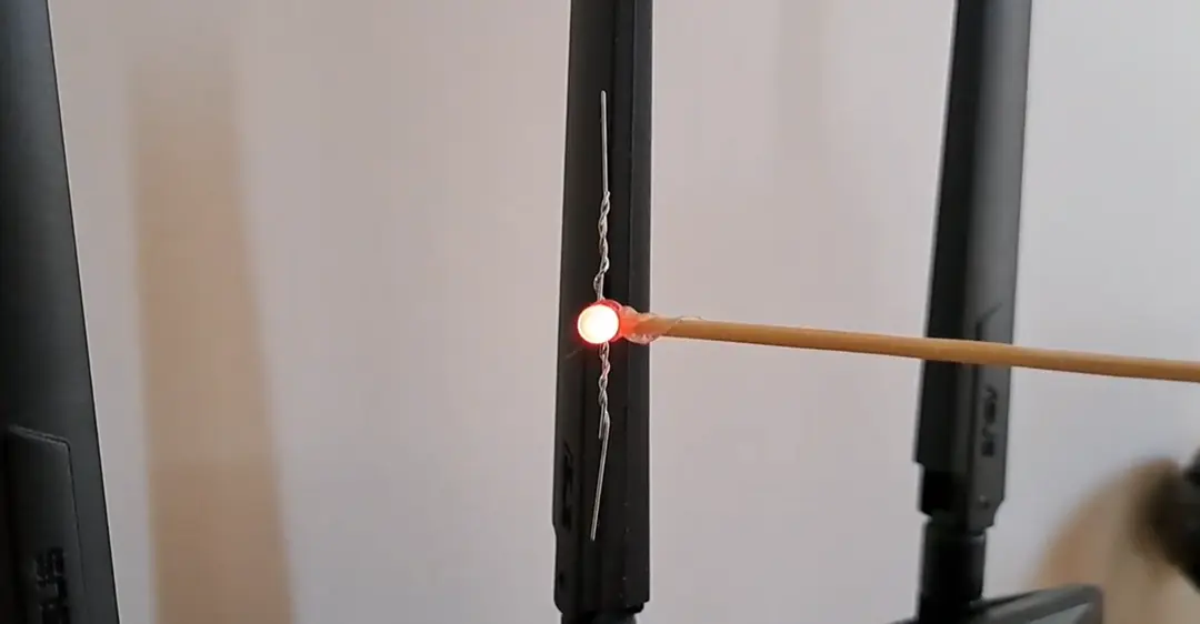
With these modifications, the Slayer Exciter circuit can handle much higher voltages without destroying your transistors. The circuit is capable of lighting fluorescent tubes from 3 to 6 inches away and even producing small sparks (around 5 mm).
In the next post, I’ll show how to build a much more powerful version of the Slayer Exciter circuit.
Here’s a sneak-peak of what the more powerful version can achieve:


Leave a Reply to Aadarsh RajCancel reply